MR8740、MR8741_user_manual_eng_20191016H.pdf - 第179页
7.9 Setting Details of Modules 167 6 Chapter 7 Utility Functions 7 Slope For each measurem ent mode, set the dire ction the specified level is exceeded. Select Devide Determines the frequen cy for each set pulse. Select …
7.9 Setting Details of Modules
166
See: Opening the [Each Ch] sheet, Making a Channel Selection (p.161)
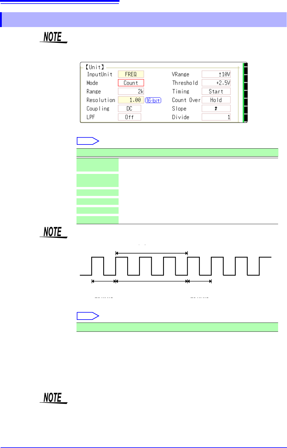
Mode Changes the measurement mode.
Select
VRange
(Input voltage)
Set the maximum level for the input signal.
Select
Threshold • When the measurement waveform exceeds the threshold value, the measure-
ment value is acquired based on the time interval and the number of times the
threshold was exceeded.
• The threshold value upper and lower limits and increases and decreases in
width depend on the input voltage ([VRange]) setting.
• While setting the threshold, the voltage level is displayed on the level monitor.
7.9.5 Setting Model 8970 Freq Unit
When the display of standard logic channels (LA and LB) is on, the 8970 Freq
Unit installed on unit 1 can no longer be used.
Selections Description
Frequency
Measure the frequency of the measurement waveform (Hz hertz)
(default setting)
RPM
Measure the number of rotations of the measurement target (r/min
rotations/minutes)
P-Freq
Measure the power frequency variation (Hz hertz)
Count
Add up the number of input pulses
Duty
Measure the duty rate of the measurement waveform (% percent)
Pulse Width
Measure the pulse width (s second)
Pulses with rises during dead time (calculation) (25 kHz or higher) cannot be
measured.
Waveform
loaded
Waveform
loaded
Calculation (40 s)
Ignored
±10 V (default setting), ±20 V, ±50 V, ±100 V, ±200 V, ±400 V
To prevent measurement errors due to noise, the threshold has a hysteresis of
approximately 3% versus the input voltage. (When
[VRange] is [ ±10 V], it is
around ±0.3 V.)
Set a threshold in excess of the hysteresis width versus the voltage peak.
7.9 Setting Details of Modules
167
6
Chapter 7 Utility Functions
7
Slope For each measurement mode, set the direction the specified level is exceeded.
Select
Devide Determines the frequency for each set pulse.
Select
Example: When the encoder is at 360 pulses per rotation, the frequency of each
rotation can be measured by setting the number of divisions to 360.
When frequency dividing is not used, set to 1.
Timing This is enabled only when [Mode] is [Count].
Sets the start timing for the sum count.
Select
Count Over This is enabled only when [Mode] is [Count].
Select
See: Opening the [Each Ch] sheet, Making a Channel Selection (p.161)
Selections Description
Rises above the specified level are detected. (default setting)
Drops below the specified level are detected.
1(default setting) to 4096
Selections Description
Start
When
[START] is clicked, summing is started.
(default setting)
Trig
When a trigger is applied, summing is started.
• When the [Start] is set, there is some internal processing time between click-
ing [START] and the start of measurement. Therefore, the count value is not
zero at the start point.
• When the [Start] is set and the trigger level is exceeded while waiting for the
pre-trigger, the trigger is not enacted. Furthermore, the time for internal pro-
cessing at start and the trigger priority setting may cause the trigger not to be
enacted at the specified trigger level.
• When memory division is used, there are cases when the last data in the previ-
ous block remains in the first part of the block.
Selections Description
Hold
Counting is performed to the maximum (at 2 k range, 65535) and
no higher.
Back
If counting is performed up to 25 times the range (at 2 k range, up
to 50000) the count value returns to 0.
7.9 Setting Details of Modules
168
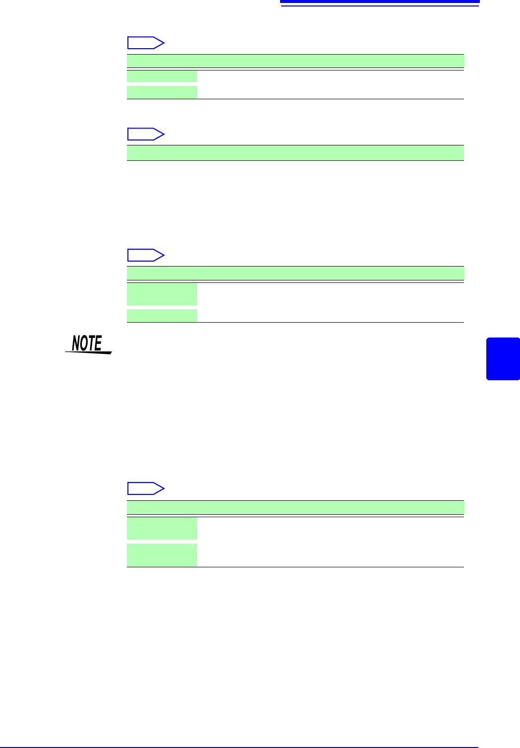
Level This is enabled only when [Mode] is [Pulse Width] or [Duty].
In pulse width/ duty rate measurements, set which level is detected when the
threshold is exceeded.
Select
See: Opening the [Each Ch] sheet, Making a Channel Selection ( p.161)
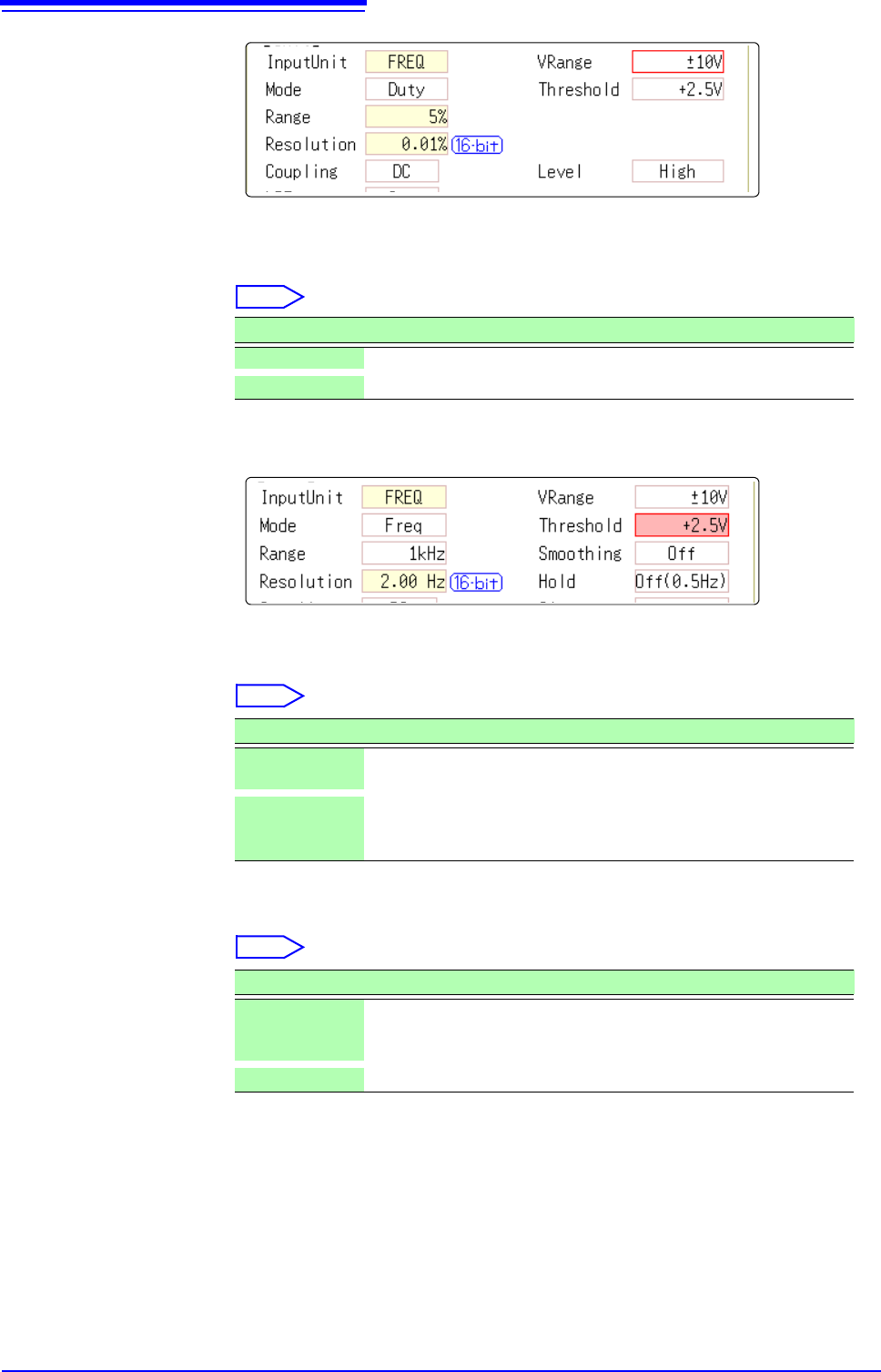
Smoothing This is enabled only when [Mode] is [Frequency] or [RPM].
Set smoothing.
Select
Hold This is enabled only when [Mode] is [Frequency] or [RPM].
Set hold for the frequency and summing.
Select
Selections Description
High Measures above the threshold value. (default setting)
Low Measures below the threshold value.
Selections Description
Off
The measured data is recorded as is. (A step waveform.)
(default setting)
On
The measured data is interpolated so that the waveform is smooth
and then it is output. (Further delayed from upper limit 10 kHz and
Off.)
Selections Description
Off
(1Hz/0.5Hz/
0.2Hz/0.1Hz)
When the frequency in the brackets is reached but not determined,
it is defined as a stopped item and the measurement value be-
comes 0 Hz (0 rpm). (default setting)
On The value defined last time is retained.