MR8740、MR8741_user_manual_eng_20191016H.pdf - 第390页
18.4 Self-Test (Self Diagnostics) 378 The following self-test checks are available. This check tests the instrument's interna l memory (ROM and RAM). 18.4 Self-T est (Self Diagnostics) Check the instrument's in…
18.3 Error Messages
377
Chapter 18 Maintenance and Service
14
18
100
Inappropriate setting of time axis for
waveform data.
Return the time axis to the time axis setting
when the waveform was measured.
"3.4.2 Time Axis Range and
Sampling Rate" (p.67)
"8.12 Using trigger settings
to search measurement da-
ta" (p.209)
101
Some blocks are different in time axis
setting from the others.
Set the same time axis setting for all search
target blocks.
If they cannot be the same, set the search
range to display blocks only.
102
Some blocks are different in units con-
figuration from the others.
Unify the unit configuration of search target
blocks.
If they cannot be the same, set the search
range to display blocks only.
"8.12 Using trigger settings
to search measurement da-
ta" (p.209)
103
No data matching your search condi-
tion.
Check the trigger setting.
104
There is no data in the search target
channel.
Select channels with measurement data in the
search target.
105
There is a block with no data in the
search target channel.
Select blocks with measurement data in the
search target.
106
Some blocks are different in measure-
ment mode of unit from the others.
Blocks different in measurement mode cannot
be searched.
-
108
Some blocks are different in measure-
ment mode of unit from the others.
Set the search range within the display blocks.
"8.12 Using trigger settings
to search measurement da-
ta" (p.209)
110
No space to store waveform data at
copy location.
Create empty space by deleting waveform
data from copy location
"7.10 Register the Waveform
in the U8793 Arbitrary Wave-
form Generator Unit" (
p.184)
111
No space to register arbitrary waveform
data.
Create empty space by deleting waveform
data from registration location.
"7.10 Register the Waveform
in the U8793 Arbitrary Wave-
form Generator Unit" (
p.184)
Displayed Warnings
Msg
No.
Message Remedial Action Reference
18.4 Self-Test (Self Diagnostics)
378
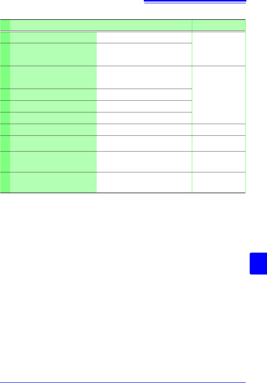
The following self-test checks are available.
This check tests the instrument's internal memory (ROM and RAM).
18.4 Self-Test (Self Diagnostics)
Check the instrument's internal memory (ROM and RAM). The results are
displayed on the screen. (p.378)
The instrument does not support the use of a printer. Clicking this has no effect.
Check the screen display (color check, gradation check). (p.379)
The instrument does not support the use of keys. Clicking this has no effect.
Check the system configuration. (p.379)
Procedure
To open the screen: Right-click and select [SYSTEM] [Init] sheet
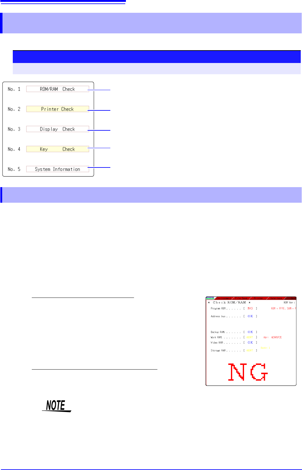
18.4.1 ROM/RAM Check
1
Move the flashing cursor to the [ROM/RAM Check] item.
2
Select [Exec].
The ROM/RAM check starts.
The following checks are performed in the sequence shown.
Program ROM
Address busBackup RAMWork RAM
Video RAMStorage RAM
Do not turn the power off during the check.
The judgment results appear when the check finishes.
OK: Normal
NG: Error
If "NG" appears, ask to have the instrument repaired.
Click the mouse to return to the previous screen.
• Performing a ROM/RAM check will cause measurement data to be erased.
Save the measurement data to other media before performing the ROM/RAM
check.
• A ROM/RAM check cannot be stopped part way through.
18.4 Self-Test (Self Diagnostics)
379
Chapter 18 Maintenance and Service
14
18
This check tests the condition of the display screen.
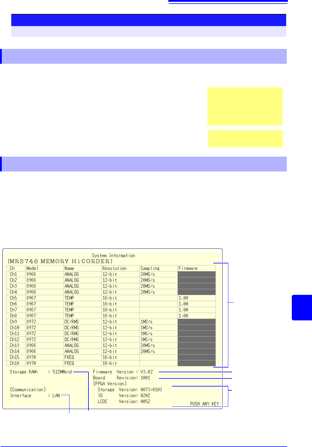
The list of installed options and other system information appears in a separate window.
Procedure (Common for Display Check, System Configuration Check)
To open the screen: Right-click and select [SYSTEM] [Init] sheet
18.4.2 Display Check
1
Move the flashing cursor to the [Display Check] item.
2
Select [Exec].
A red screen appears.
3
Check the condition of the display.
Left-click the mouse to change the screen.
The original screen reappears
If the display screen seems ab-
normal, request repairs.
Screen Changes
Color check (Red, Green, Blue,
Black, White) Gradiation
check (Red, Green, Blue, Black,
White) Color patternOriginal
screen.
18.4.3 System Configuration Check
Currently selected
interface
1
Move the flashing cursor to the [System Information] item.
2
Select [Exec].
The System Configuration List appears.
To reappear the original screen:
Left-click the mouse.
Model number, name,
resolution and sampling
rate of each installed
module (unit)
Firmware version no.
Board revision no.
FPGA version no.
Internal memory
capacity