MR8740、MR8741_user_manual_eng_20191016H.pdf - 第170页
7.6 Fine Adjustment of Input Values (Vernier Function ) 158 Fine adjustment of input voltage can be performed arbitrarily on the Wave form screen. When recording physical values such as noise, tem per ature and accelerat…
7.5 Variable Function (Setting the Waveform Display Freely)
157
6
Chapter 7 Utility Functions
7
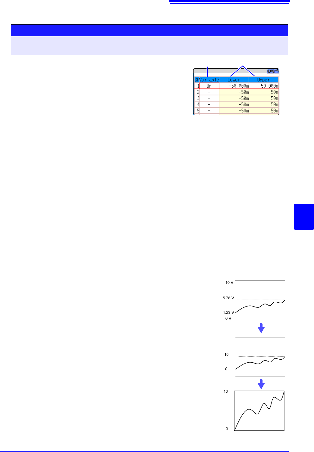
Displaying All Channels for Making the Variable Function Setting ______
Description
When setting combined use of the Scaling and Variable functions
When Auto-Correction of the Variable function is enabled (On, default set-
ting) (p.311)
The Variable function settings change according to Scaling and vertical axis
(voltage axis) range settings. Set Scaling before setting the Variable function.
If you change Scaling settings after enabling the Variable function, the Variable
setting voltage is automatically corrected so that the displayed size of waveforms
is unchanged.
When Auto-Correction of the Variable function is disabled (Off)
Set the Variable function after setting Scaling.
If setting the Variable function first, enter post-scaling values (converted physical
values).
To display the full span of output from a sensor
By using the Scaling function in combination, voltage from a sensor can be con-
verted to the physical units of the measurement object.
Procedure
To open the screen: Right-click and select [DISP] Waveform screenRight-click and select [CH.SET]
Display range window
1
Enable the Variable function.
Move the flashing cursor to the [Variable], and select [On].
2
Set the upper and lower limits.
Move the flashing cursor to the [Upper] and [Lower], and
enter numerical value.
12
A
A
A
A
Example:
Set Scaling as follows:
Scaling: Decimal or exponent, Two-Point Setting
Units: A
Sensor Output (Input 1): 1.23 [V]
(Scale 1): 0 [A]
Sensor Output (Input 2): 5.78 [V]
(Scale 2):10 [A]
(with Variable function Off)
Voltage from the sensor is displayed as voltage.
It is displayed with the vertical axis (voltage axis) range
and at the zero position set on the Channel settings win-
dow (
[Analog] sheet).
The Variable function is set as follows:
Variable: On, Set Upper/Lower Limits
Lower Limit: 0 [A] Upper Limit: 10 [A]
The full span of output from the sensor is displayed.
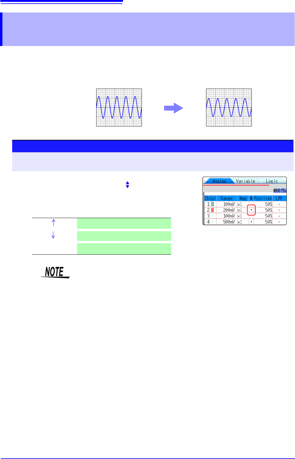
7.6 Fine Adjustment of Input Values (Vernier Function)
158
Fine adjustment of input voltage can be performed arbitrarily on the Waveform screen. When
recording physical values such as noise, temperature and acceleration using sensors, amplitude
can be adjusted to facilitate calibration.
7.6 Fine Adjustment of Input Values (Vernier
Function)
Normal Display Vernier Function Enabled
1.2 V input is displayed as 1.0 V
1.2 V
1.0 V
Procedure
To open the screen: Right-click and select [DISP] Waveform screen Right-click and select [CH.SET]
Channel settings window ([Analog] sheet)
1
Move the flashing cursor to the [] vernier setting item of
the channel to adjust.
2
Make the adjustment while watching the waveform.
Vernier Magnify waveform
Vernier
Compress waveform
Vernier Reset
Return waveform to original position
• The adjustment range is 50 - 200% of the original waveform. The magnifica-
tion/compression ratio is not displayed.
• Vernier adjustments cannot be verified on waveforms.
• The waveform data (saved file data) is adjusted by the Vernier function.
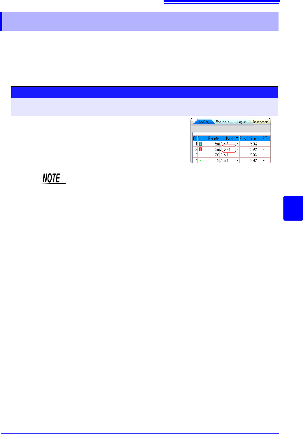
7.7 Inverting the Waveform (Invert Function)
159
6
Chapter 7 Utility Functions
7
This applies to the analog channels only. You can invert the plus and minus sides of the waveform.
Example: • When a current sensor is clamped around a wire with its current direction
mark mistakenly in the direction opposite to the current flow
• When a signal is inputted with spring-pulling force negative and spring-com-
pressing force positive; however, you would like to display the results with
spring-pulling force positive and spring-compressing force negative
7.7 Inverting the Waveform (Invert Function)
Procedure
To open the screen: Right-click and select [DISP] Waveform screen Right-click and select [CH.SET]
Channel settings window ([Analog] sheet)
1
Move the flashing cursor to the [Mag] item for the channel
whose waveform you want to invert.
2
Select [Invert].
The waveform data (saved file data) is adjusted by the Invert function.