MR8740、MR8741_user_manual_eng_20191016H.pdf - 第50页
2.1 Installing and Removing Modules 38 MR8741 The module numbers ar e in order starting with one at the left, and th e channel numbers ar e in order starting with one at the bottom of the modu le at the very left. Analog…
2.1 Installing and Removing Modules
37
2
Chapter 2 Measurement Preparations
About channel
allocation
Information about the modules installed the instrument can be verified in the
System Configuration list (p.346).
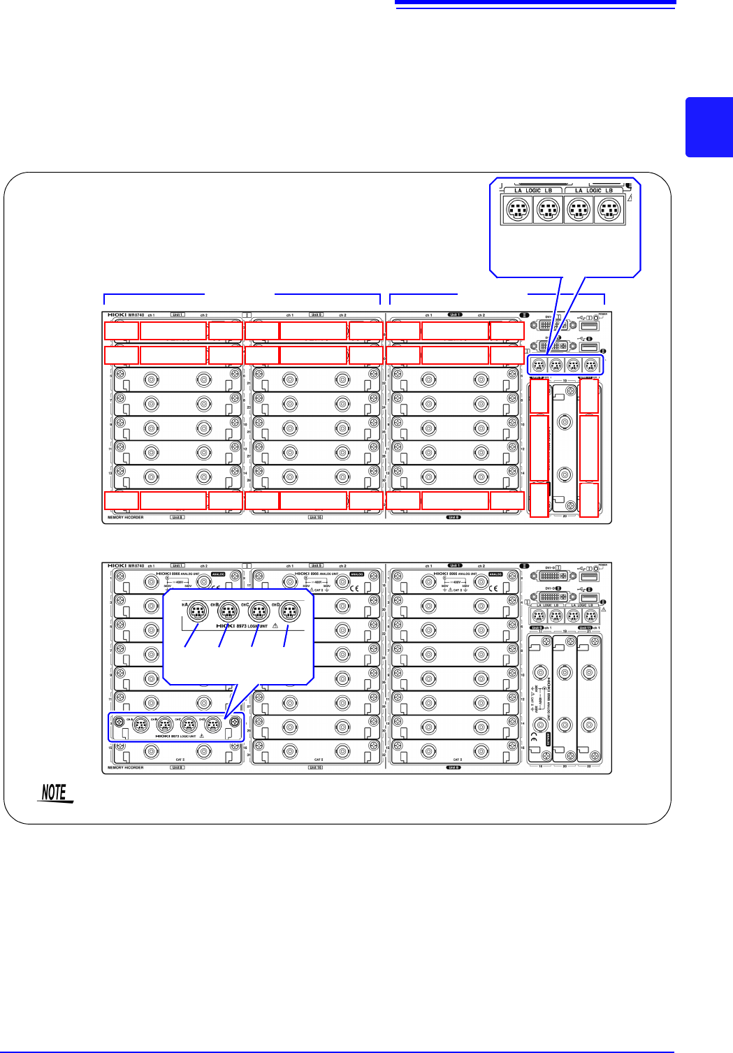
MR8740 The instrument has a two-block configuration consisting of Block I and Block II.
For each block, the module numbers are in order starting with one at the top, and
the channel numbers are in order starting with one on the left of the module at
the very top.
Analog channels only
Block I Block II
LA LB LA LB
[1:4] [1:4] [1:4] [1:4]
Mix including logic units
L7A L7B L7C L7D
[1:4] [1:4] [1:4] [1:4]
Install the logic units at the module 1 to module 8 positions on both blocks. Even if you
install logic units for module 9 and after, they will be invalid.
Ch1
Module 1
Ch2
Ch3
Module 2
Ch4
Ch15
Module 8
Ch16
Ch17
Module 9
Ch18
Ch19
Module 10
Ch20
Ch31
Module 16
Ch32
Ch17
Module 9
Ch18
Ch21
Module 11
Ch22
Block I Block II
Ch1
Module 1
Ch2
Ch3
Module 2
Ch4
Ch15
Module 8
Ch16
2.1 Installing and Removing Modules
38
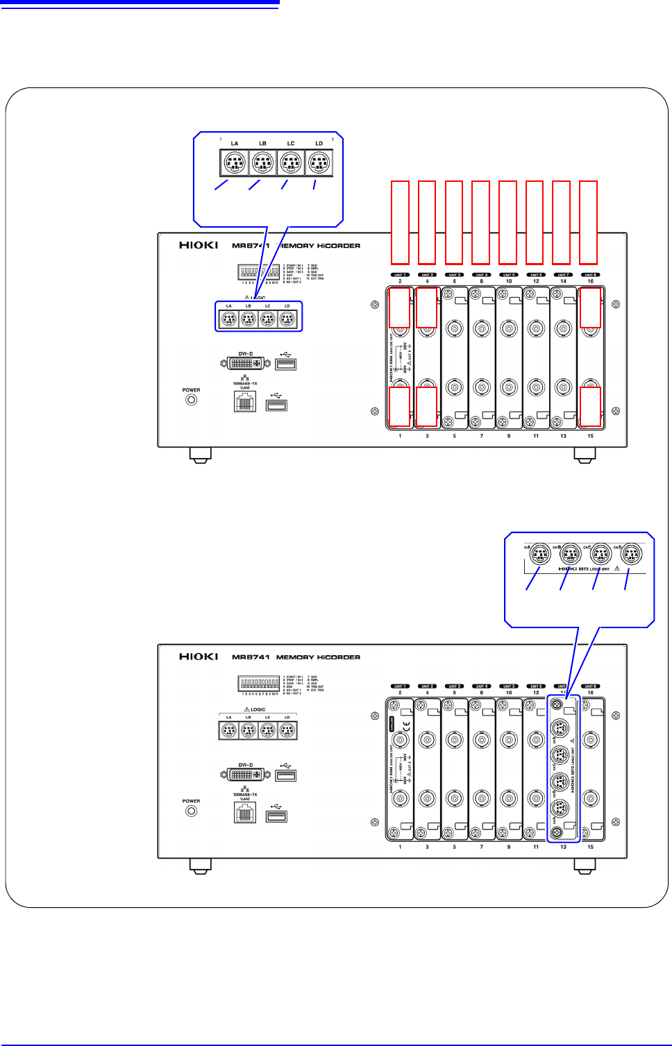
MR8741 The module numbers are in order starting with one at the left, and the channel
numbers are in order starting with one at the bottom of the module at the very
left.
Analog channels only
Ch1 Ch2
LA LB LC LD
[1:4] [1:4] [1:4] [1:4]
Module 1
Module 2
Module 3
Module 4
Module 5
Module 6
Module 7
Module 8
Mix including logic units
Ch3 Ch4
Ch15 Ch16
L7A L7B L7C L7D
[1:4] [1:4] [1:4] [1:4]
2.2 Connecting Cords
39
2
Chapter 2 Measurement Preparations
Read "Before Connecting Cables" ( p.11) carefully.
For detailed precautions and instructions regarding connections, refer to the instruction manuals for your
modules, connection cables, etc.
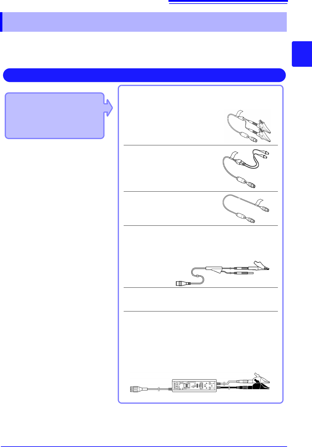
2.2 Connecting Cords
Applicable Modules
• 8966 Analog Unit
• 8968 High Resolution Unit
• 8972 DC/RMS Unit
• U8979 Charge Unit
Use to connect: Connection cords
• L9197 Connection Cord
(Maximum input voltage: 600 V)
Large alligator clip type
• L9198 Connection Cord
(Maximum input voltage: 300 V)
Small alligator clip type
• L9217 Connection Cord
(Maximum input voltage: 300 V)
For measuring BNC output
• L9790 Connection Cord
(Maximum input voltage: 600 V)
Terminal type: Alligator, contact, grabber
Example: Terminal type: Alligator
• 9166 Connection Cord
(Maximum input voltage: 30 V AC, 60 V DC)
Electrical clips
When a voltage to be measured exceeds a maximum input rating
of a module being used
• Model 9322 Differential Probe
*1
• Model 9665 10:1 Probe
• Model 9666 100:1 Probe
• Model P9000-01/-02 Differential Probe
*2
Example: Model P9000-02 Differential Probe
Measuring Voltage
Connect to the BNC jack on a module.
*1 An optional power cord or AC adapter is
required.
*2 An optional AC adapter or a commercially
available USB cable is required.