MR8740、MR8741_user_manual_eng_20191016H.pdf - 第195页
7.9 Setting Details of Modules 183 6 Chapter 7 Utility Functions 7 Method Selects the control method fo r waveform output. Select Settings when selecting arbitrary waveform Data name Register/de lete the data of the outp…

7.9 Setting Details of Modules
182
Offset For DC output: Sets DC voltage.
For sine wave output: Sets the offset voltage.
The output voltage with guaranteed accuracy is the sum of the amplitude and the
offset, between -10 V and +10 V. If the sum of the amplitude and the offset is set
outside the guaranteed accuracy range, parts of the waveform will be clamped to
the upper limit, approximately +16 V and the lower limit, approximately -11 V.
Phase Sets the phase.
Duty Sets the duty when selecting pulse wave.
When Off Sets the output terminal status when the output is off.
Select
Output Turns waveform output On/Off.
Select
Control Sets the waveform output.
Select
-10 V to +15 V
-360 to 360
0.1% to 99.9%
Selections Description
Open Opens the output terminals, separating them from internal circuits.
Short Short-circuits the output terminals, separating them from internal
circuits.
Selections Description
On Outputs waveform.
Off Does not output the waveform.
Selections Description
RUN Starts output. (Output indicator: Red)
PAUSE Pauses output. While output is paused, the output at the time
[PAUSE]
was pressed will be output. (Output indicator: Red)
STOP Stops output. (Output indicator: Off)

7.9 Setting Details of Modules
183
6
Chapter 7 Utility Functions
7
Method Selects the control method for waveform output.
Select
Settings when selecting arbitrary waveform
Data name
Register/delete the data of the outputted waveform. Maximum eight waveforms
can be registered.
Filter Filter the output waveform.
Clock Freq Set the clock frequency of the D/A converter that generates waveforms.
The period and frequency of the output waveform are displayed on the lower
level.
Delay Set the delay for waveform generation. When the delay value is positive, the
phase is progressive.
Loop Set the repetition count for generating waveforms.
Amp Adj Set the amplitude level for waveform output.
Offset Set the offset voltage for waveform.
Selections Description
Manual Restricts control of signal output to Signal Generation screen.
Sync. Augments manual control with signal output in synchronization with
the start and end of measurement.
START key: Starts output when measurement starts.
STOP key: Stops output when measurement stops.
Keys Augments manual control by allowing signal output to be manipu-
lated using the instrument’s keys.
START key: Starts output.
STOP key: Stops output.
Manual Trigger key: Pauses output.
Off (Default setting) to 1 MHz
-250,000 data to 250,000 data (Default settings: 0)
1 to 50,000, (Default setting: )
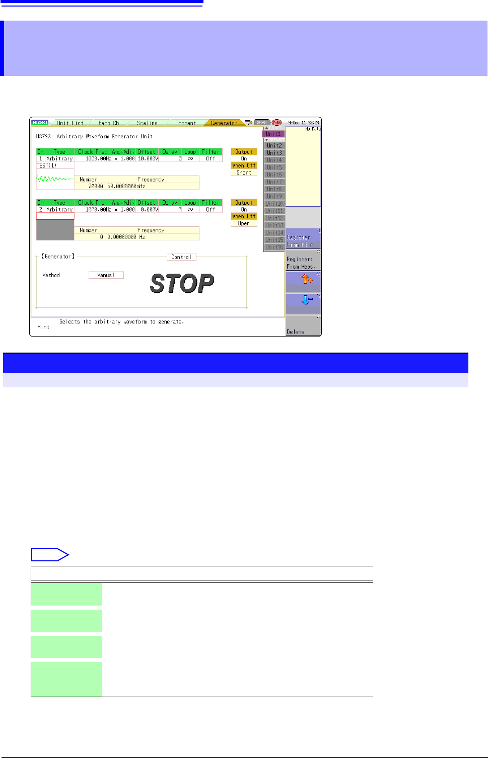
7.10 Register the Waveform in the U8793 Arbitrary Waveform Generator Unit
184
You can register waveform in the Model U8793. Registered waveforms can be output from the Model U8793.
7.10 Register the Waveform in the U8793 Arbi-
trary Waveform Generator Unit
Procedure
To open the screen: press the CHAN key to open the Channel screen, and then select [Generator] sheet
1
Set the type to arbitrary waveform.
Move the cursor to [Type] on the settings screen, and select [Arbitrary] using the F keys.
2
Register the waveform.
Move the cursor to the item listed below [Arbitrary] on the settings screen.
3
Select a reading source of the waveform.
Select
Selections Description
Resister:
From File
Registers from data saved in the media.
Register:
From Meas.
Registers the data measured using memory function. You can also
register after reading the MEM files from media to the instrument.
or Select arbitrary waveform data registered in the Model U8793.
(Use when selecting/deleting output waveforms.)
Delete Deletes the data registered in the U8793 memory.
If eight waveforms are already registered in the memory, delete
any of them and then register.