MR8740、MR8741_user_manual_eng_20191016H.pdf - 第74页
3.2 Measurement Workflow 62 3.2 Measurement W orkflow 2 Make basic setting s for measurement Set waveform length Select suitable re cording method for measur ement target Set dat a acquisition speed Set waveform display …
3.1 Ensuring Measurement Safety
61
3
Chapter 3 Measurement Procedure
7
Be sure to observe the following points, to ensure safe measurement.
Measurement
Procedure Chapter 3
3.1 Ensuring Measurement Safety
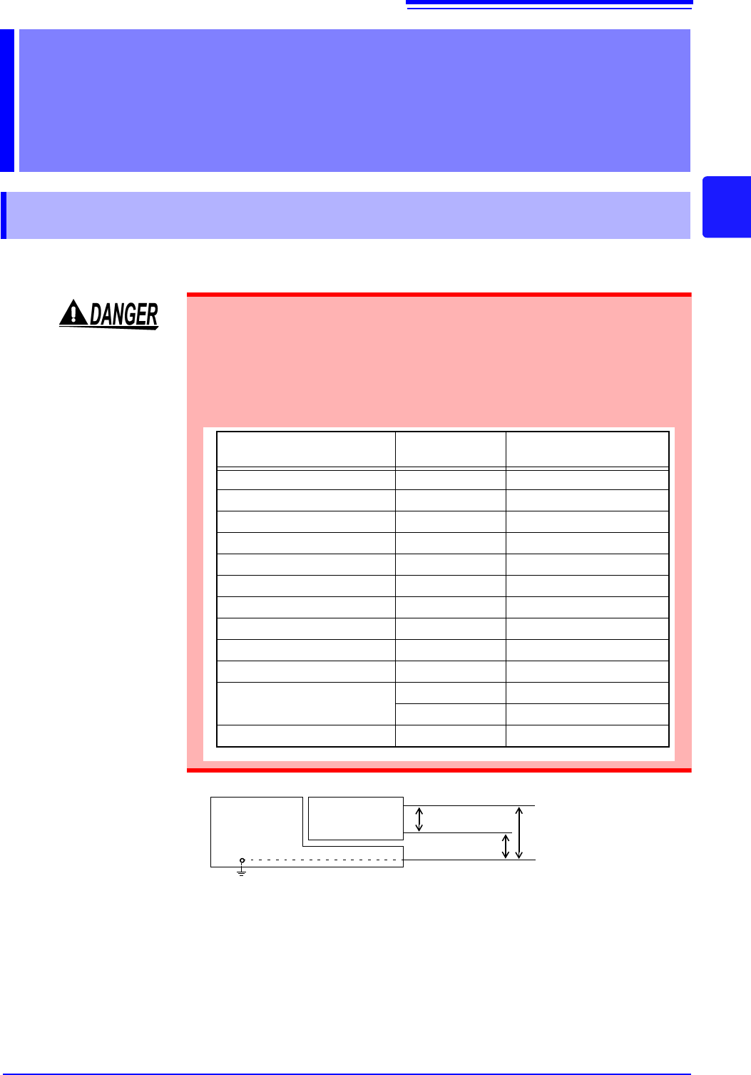
The maximum rated input voltage and maximum rated voltage versus ground
values for modules and connection cables are listed in the table below. In order
to prevent the risk of electric shock and damage to the equipment, make sure
that these voltages are not exceeded.
The maximum rated voltage versus ground does not change also when an atten-
uator or similar is used at the input. Take the connection method into consider-
ation and make sure that the rating is not exceeded.
Module
Maximum rated
input voltage
Maximum rated voltage
versus ground
8966 Analog Unit 400 V DC 300 VAC/DC (CAT II)
8967 TEMP Unit - 300 VAC/DC (CAT II)
8968 High Resolution Unit 400 V DC 300 VAC/DC (CAT II)
8969 Strain Unit - 33 V rms / 70 V DC
U8969 Strain Unit - 30 V rms / 60 V DC
8970 Freq Unit 400 V DC 300 V AC/DC (CAT II)
8971 Current Unit - Not insulated.
8972 DC/RMS Unit 400 V DC 300 V AC/DC (CAT II)
8973 Logic Unit - Not insulated.
MR8990 Digital Voltmeter Unit 500 V DC AC/DC 300 V (CAT II)
U8974 High Voltage Unit
1000 V DC 1000 V AC/DC (CAT III)
700 V AC 600 V AC/DC (CAT IV)
U8979 Charge Unit 40 V DC 30 V AC, 60 V DC
MR8740/
MR8741
Memory HiCorder
Module
GND
Maximum rated
input voltage
H
L
Maximum rated volt-
age versus ground
3.2 Measurement Workflow
62
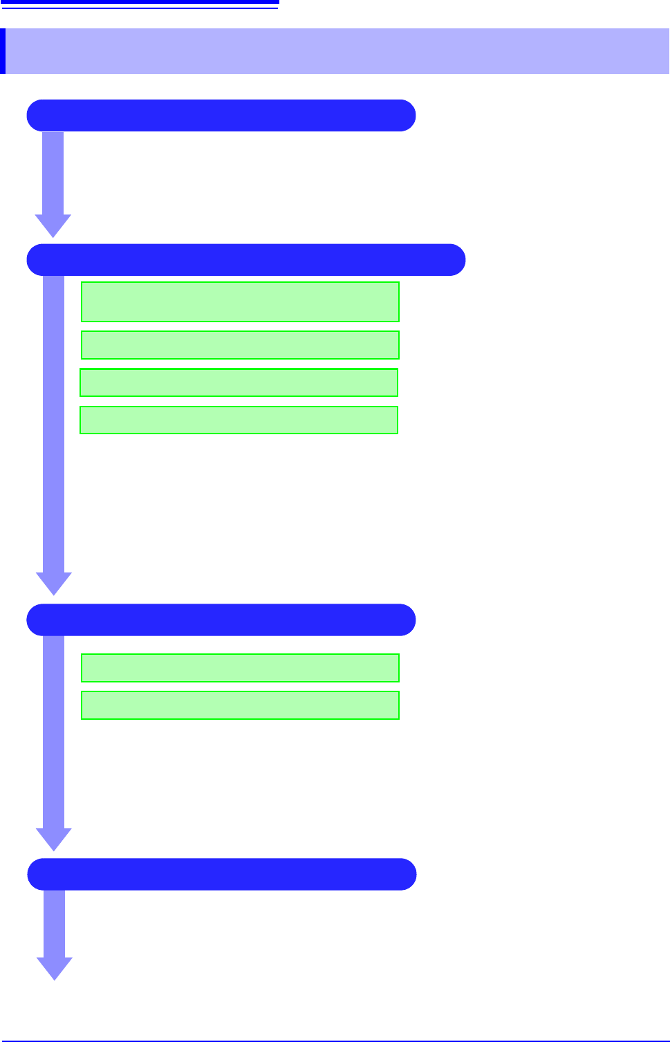
3.2 Measurement Workflow
2 Make basic settings for measurement
Set waveform length
Select suitable recording method for
measurement target
Set data acquisition speed
Set waveform display format
See:
"3.4.1 Measurement Function" (p.65)
"3.4.2 Time Axis Range and Sampling Rate"
(p.67)
"3.4.3 Recording Length (number of divisions)"
(p.70)
"3.4.4 Screen Layout" (p.72)
Application examples
See:
"6.4 Performing Waveform X-Y Synthesis" (p.127)
"7.2 Displaying Waveforms During Recording (Roll Mode)" (p.145)
"7.3 Displaying New Waveforms Over Past Waveforms (Overlay)" (p.146)
"Chapter 9 Numerical Calculation Functions" (p.211)
3 Input Channel Settings
Make analog channel settings
Make logic channel settings
See:
"3.5.2 Analog Channel" (p.76)
"3.5.3 Logic Channel" (p.79)
Application examples
See:
"7.1 Adding Comments" (p.138)
"7.4 Converting Input Values (Scaling Function)" (p.148)
"7.5 Variable Function (Setting the Waveform Display Freely)" (p.155)
"7.6 Fine Adjustment of Input Values (Vernier Function)" (p.158)
"7.7 Inverting the Waveform (Invert Function)" (p.159)
4 Make trigger settings
See:
"Chapter 8 Trigger Settings" (
p.189)
1 Pre-Measurement Inspection
See:
"3.3 Pre-Measurement Inspection" (p.64)
3.2 Measurement Workflow
63
3
Chapter 3 Measurement Procedure
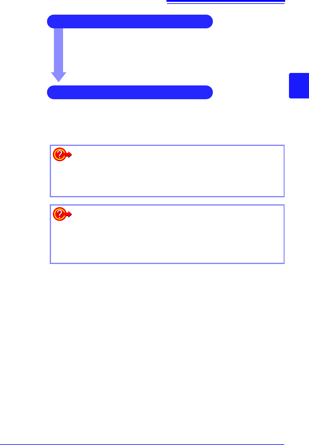
5 Starting Measurement
See:
"3.6 Starting and Stopping Measurement" (p.81)
"Chapter 4 Saving/Loading Data & Managing Files" (p.83)
"6.1 Reading Measurement Values (Using the A/B Cursors)" (p.120)
"6.3.2 Scrolling the Measurement Waveform" (p.125)
"6.5 Magnifying and Compressing Waveforms" (p.129)
6 Stopping Measurement
See:
"3.6 Starting and Stopping Measurement" (p.81)
To reuse previously stored settings
Load the settings file from the File screen.
Saving the settings for different measurement targets or applications enhances
operation convenience.
See: "4.3 Loading Data" (p.99)
To return settings to the original (basic default) condition
From the System screen, select the [Init] sheet to return the unit to the factory
default settings. In this condition, the unit is set up to easily perform simple
measurements. If operation of the unit seems unusual or overly complex, per-
form the initialization procedure.
See: "18.2 Initializing the Instrument" (p.374)