MR8740、MR8741_user_manual_eng_20191016H.pdf - 第168页
7.5 Variable Function (Setting the Wa veform Display Freely) 156 Make the V aliable Function Setti ng per channel _____________________ Procedure To open th e screen : Right-clic k and select [CHAN] [Each Ch] sheet 1…
7.5 Variable Function (Setting the Waveform Display Freely)
155
6
Chapter 7 Utility Functions
7
The waveform height and display position can be arbitrarily set along the vertical axis (voltage axis).
The following two setting methods are available:
• Set the displayed amplitude per division (1div setting)
Set the amplitude to be displayed per vertical division and the zero position of
the waveform on the vertical axis (voltage axis).
• Set the Upper and Lower Limits (Upper-Lower setting)
The upper and lower limits on the vertical axis (voltage axis) can be set to dis-
play the waveform amplitude full-screen.
Settings for the Variable function can be made for each individual channel, using
the [Each Ch] sheet accessed from the Channel screen (p.156), or for all chan-
nels using the Display range window (p.157).
7.5 Variable Function (Setting the Waveform Dis-
play Freely)
Precautions for using the Variable Function
• Verify that the vertical axis (voltage axis) range is set properly for the input sig-
nal.
• The vertical axis (voltage axis) range is unaffected by changes to the upper
and lower limits made by the Variable setting.
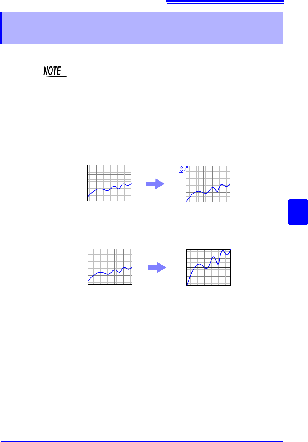
Normal Waveform
Variable Function (Per-Division setting)
0V
10V
0V
1V
Per Division: 1 V
Zero Position: 0%
Normal Waveform Variable Function (Set Upper/Lower Limits)
0V
10V
0V
10V
Upper Limit: 10 V
Lower Limit: 0 V
7.5 Variable Function (Setting the Waveform Display Freely)
156
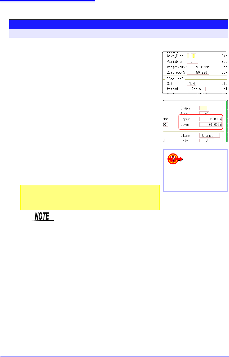
Make the Valiable Function Setting per channel _____________________
Procedure
To open the screen: Right-click and select [CHAN] [Each Ch] sheet
1
2
3
1
Enable the Variable function.
Move the flashing cursor to the [Variable], and select [On].
2
Set the display range per division
Move the flashing cursor to the [Range(div)], and enter numeri-
cal value.
(Measurement units depend on the measurement mode of the module.)
(When this is changed, the upper/lower limit values for the display also change ac-
cordingly.)
3
Set the waveform zero position to display on the vertical
axis (vertical axis).
Move the flashing cursor to the [Zero pos%], and enter numeri-
cal % value.
(When this is changed, the upper/lower limit values for the display also change ac-
cordingly.)
4
(When setting upper and lower values)
Move the flashing cursor to the [Upper] and [Lower], and specify the
values.
(When this is changed, the display range and zero position values also change ac-
cordingly.)
4
To reset the settings
Select [Reset] to return the set-
tings to the default values.
• When upper and lower values are set, waveforms can be displayed at full
span on the screen.
• Depending on the scaling setting, the upper and lower display values may be less
than 1. In such cases, set [Variable] to [On] and then select [Auto Set]. Easy-
to-read upper and lower limit values are set based on the currently set values.
• For information on numeric input, see "7.1.3 Alphanumeric Input" (p.141).
•The [Unit List] sheet accessed from the Channel screen also lets you turn the
Variable function On or Off individually for each channel.
• By using the Scaling and Variable functions together, the full span of a sen-
sor's output can be displayed. (p.157)
• When Scaling is enabled, values are displayed in scaling units. When these
settings are changed, the numerical values indicating the display range on the
level monitor are changed accordingly.
7.5 Variable Function (Setting the Waveform Display Freely)
157
6
Chapter 7 Utility Functions
7
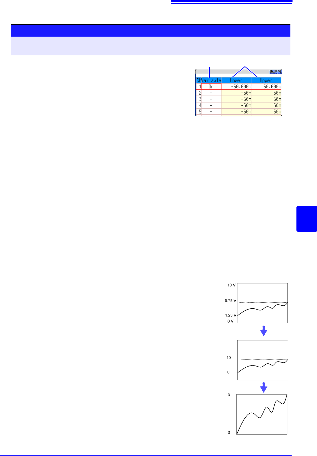
Displaying All Channels for Making the Variable Function Setting ______
Description
When setting combined use of the Scaling and Variable functions
When Auto-Correction of the Variable function is enabled (On, default set-
ting) (p.311)
The Variable function settings change according to Scaling and vertical axis
(voltage axis) range settings. Set Scaling before setting the Variable function.
If you change Scaling settings after enabling the Variable function, the Variable
setting voltage is automatically corrected so that the displayed size of waveforms
is unchanged.
When Auto-Correction of the Variable function is disabled (Off)
Set the Variable function after setting Scaling.
If setting the Variable function first, enter post-scaling values (converted physical
values).
To display the full span of output from a sensor
By using the Scaling function in combination, voltage from a sensor can be con-
verted to the physical units of the measurement object.
Procedure
To open the screen: Right-click and select [DISP] Waveform screenRight-click and select [CH.SET]
Display range window
1
Enable the Variable function.
Move the flashing cursor to the [Variable], and select [On].
2
Set the upper and lower limits.
Move the flashing cursor to the [Upper] and [Lower], and
enter numerical value.
12
A
A
A
A
Example:
Set Scaling as follows:
Scaling: Decimal or exponent, Two-Point Setting
Units: A
Sensor Output (Input 1): 1.23 [V]
(Scale 1): 0 [A]
Sensor Output (Input 2): 5.78 [V]
(Scale 2):10 [A]
(with Variable function Off)
Voltage from the sensor is displayed as voltage.
It is displayed with the vertical axis (voltage axis) range
and at the zero position set on the Channel settings win-
dow (
[Analog] sheet).
The Variable function is set as follows:
Variable: On, Set Upper/Lower Limits
Lower Limit: 0 [A] Upper Limit: 10 [A]
The full span of output from the sensor is displayed.