KJ-01.02.Instruction Manual.REV.02.pdf - 第102页
5 − 6 5.1.7 Exit W hen y ou select the [ Exit] command, t he dialog box appears on the screen t hat asks you wheth er to set the sa fety directi on of each I/O de vice . W hen y ou click the <YES> but ton, t he “Tu…
5 − 5
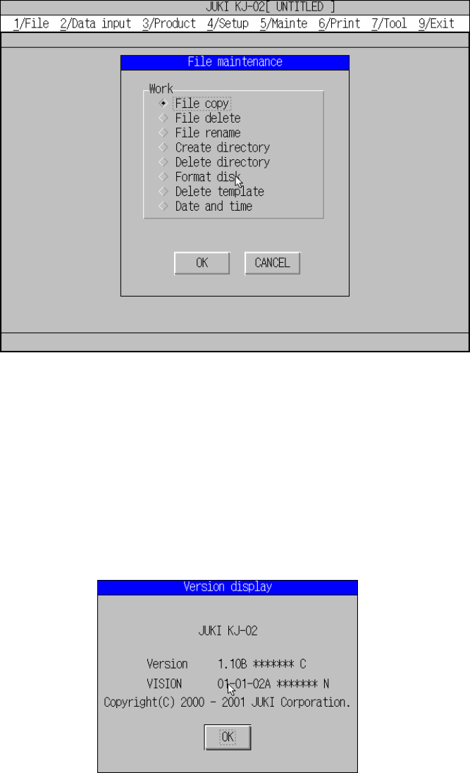
5.1.5 File maintenance
A screen appears as shown in Figure 5.1.5.1 “File maintenance dialog box” when
[File maintenance] is selected from the File menu.
Figure 5.1.5.1 File maintenance dialog box
This dialog box can be used for file management. See Chapter 8 “FILE
MANAGEMENT” for details.
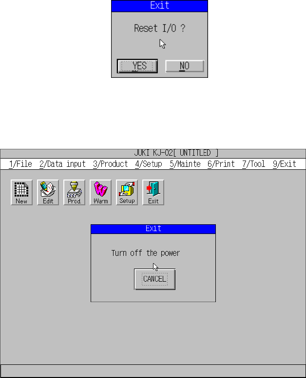
5.1.6 About program
A screen appears as shown in Figure 5.1.6.1 when [About program] is selected from
the File menu.
Figure 5.1.6.1 About program
The version number of this program and that of the VCS appear on the screen
above.
5 − 6
5.1.7 Exit
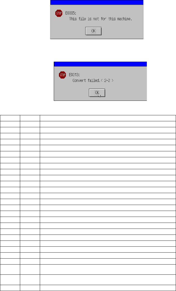
When you select the [Exit] command, the dialog box appears on the screen that asks
you whether to set the safety direction of each I/O device.
When you click the <YES> button, the “Turn off the power” screen appears. Be sure
to turn off the machine only after this screen appears.
5 − 7
Notes
−
If you load a production program created with a KE-750 or KE-760 to the machine,
the machine converts it to the production program in the KJ-02 format: only PWB
data, Placement data and Component data (component names only) of a
production program are converted.
−
Any component name of some KE-750/KE-760 production programs may not be
displayed, or a component name that is not recorded in Placement data may be
displayed.
−
The machine will not convert any production program created with a
KE-750/KE-760 whose version number is earlier than 1.25.
The following error dialog box appears on the screen.
If a conversion error occurs, the following error message appears on the screen,
and the machine stops its data conversion process.
Description of conversion error messages <x-y>
X Y Error description
1 0 PWB data is not complete.
1 1 The PWB home position X is out of the allowable data range.
1 2 The PWB home position X is out of the allowable data range.
1 3 The BOC mark position 1X is out of the allowable data range.
1 4 The BOC mark position 1Y is out of the allowable data range.
1 5 None
1 6 The BOC mark position 2X is out of the allowable data range.
1 7 The BOC mark position 2Y is out of the allowable data range.
1 8 None
1 9 The BOC mark position 3X is out of the allowable data range.
1 10 The BOC mark position 3Y is out of the allowable data range.
1 11 None
1 12 The bad mark position X is out of the allowable data range.
1 13 The bad mark position Y is out of the allowable data range.
1 14 The PWB height is out of the allowable data range.
1 15 The first circuit position X is out of the allowable data range.
1 16 The first circuit position Y is out of the allowable data range.
1 17 The circuit division number X is out of the allowable data range.
1 18 The circuit division number Y is out of the allowable data range.
1 19 The circuit pitch X is out of the allowable data range.
1 20 The circuit pitch Y is out of the allowable data range.
1 21 The non-matrix data X is out of the allowable data range.
1 22 The non-matrix data Y is out of the allowable data range.
1 23 The non-matrix data angle is out of the allowable data range.
2
1
The component placement position X is out of the allowable data
range.
2
2
The component placement position Y is out of the allowable data
range.
2 3 The component placement angle is out of the allowable data range.