KJ-01.02.Instruction Manual.REV.02.pdf - 第368页
13 − 6 13.5 Handling the Bad M ark Sensor Figure 13.5.1 Note: Do not change the set ting of the L- ON/D-O N switch (s etting at t he factory: D-ON) . 1) Color and size of a bad mark a) A bad mar k on a PC board t o which…
13 − 5
13.4
Procedure for Mounting the Matrix Tray Holder on the Feeder Bank
(See Figure 13.4.1.)
CAUTION
To avoid any accident caused by sudden activation of the machine, turn off
the power.
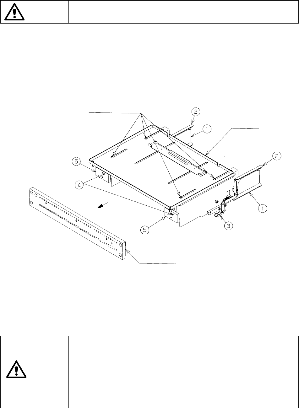
1) Grip the side plate ① and lock lever ② to open the lock holder ③.
2) Insert the front pin ④ into the fixing plate of the rear bank.
3) Release the side plate ① and lock lever ② when the front plate ⑤ into which
the pin ④ is inserted is in contact with the fixing plate, then lock these plates
with the lock holder ③.
4) To detach the matrix tray holder, follow this procedure in the reverse order.
① Side plate
② Tray lock lever
③ Lock holder
④ Pin
⑤ Front plate
Figure 13.4.1
CAUTION
To prevent your body from injury and to avoid damage to the machine,
mount a tray on the matrix tray holder only after you remove the matrix tray
holder from the feeder bank or after you check to see if the main unit
completely stops.
If you mount a tray on the matrix tray holder although the matrix tray holder
is being installed on the feeder bank, be sure to check your environment
before mounting a tray so that the machine cannot start unexpectedly
when another operator operates the machine by mistake.
Top plate
Fixing plate
M3 Hexagonal-hole-headed bolts (four)
13 − 6
13.5 Handling the Bad Mark Sensor
Figure 13.5.1
Note: Do not change the setting of the L-ON/D-ON switch (setting at the factory:
D-ON).
1) Color and size of a bad mark
a) A bad mark on a PC board to which green resist is applied shall be a glossy
white mark of 2.5 mm in diameter or greater.
b) A bad mark on a white ceramic PC board shall be a black mark of 2.5 mm in
diameter or greater.
c) The bad-mark reader cannot recognize the smaller or faded marks. The bad
marks shall be clear and legible.
2) How to set the sensitivity of the bad mark sensor
− Since the sensitivity of the bad mark sensor is set at the factory, do not touch
the mode switch or tuning button easily.
− The bad mark sensor cannot detect a bad mark easily depending on the color
of a board or mark. In such a case, set the sensitivity of the bad mark sensor
as described in the following procedure.
CAUTION
To avoid risk of injury, set the sensitivity of the bad mark sensor only after
you open the cover, and check to see if the main unit comes to halt
completely.
Be carefully to attach the bad mark sensor on the machine so that any
wrong operation of a person working an internal part cannot cause the
machine to start up unexpectedly.
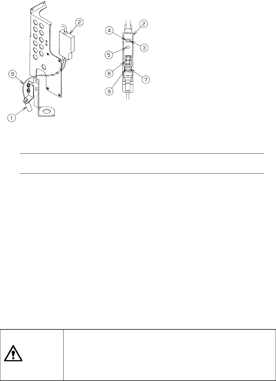
① Detecting head
② Bad mark sensor amplifier
③ Mode switch
④ L-ON/D-ON switch
(decides whether the sensor is
turned ON when receiving light or
when shutting light).
⑤Auto tuning button
⑥Digital display
⑦Stability light (green)
⑧Operation light (red)
⑨Fiber
13 − 7
<Procedure for setting the sensitivity of the bad mark sensor>
1. Set the Mode switch to “SET”. “1” appears on the digital display.
2. Align the red spot of a bad mark with a mark of a board.
3. Press the tuning button once.
“2” appears on the digital display.
Check to see if only the green LED flashes.
4. Move the red spot of the bad mark outside a mark of the board.
5. Press the tuning button once.
A value from “1” to “9” (detection margin) appears on the digital display.
Check to see if the green LED lights up.
6. Set the Mode switch to “RUN.”
A value from “1” to “9” (received light level) appears on the digital display.
The following two types errors may occur.
If an error occurs, set the sensitivity of the bad mark sensor again.
1. Insufficient sensitivity: ..........The red LED flashes (green LED goes off), and “E”
flashes on the digital display. Note that the red and
green LEDs flash and “2” appears on the digital
display at Step 3.
2. Insufficient level difference: .The red LED lights up (green LED goes off), and “E”
appears on the digital display.