KJ-01.02.Instruction Manual.REV.02.pdf - 第21页
1 − 5 0.45 Figure 1.1.2. 4 OFP/BQFP PLCC Electrolytic capacitor (Between the bottom s urface of the mold and t he foot of the leads) Laser align meas urement positi on (Between the bottom s urface of the mold and t he fo…
1 − 4
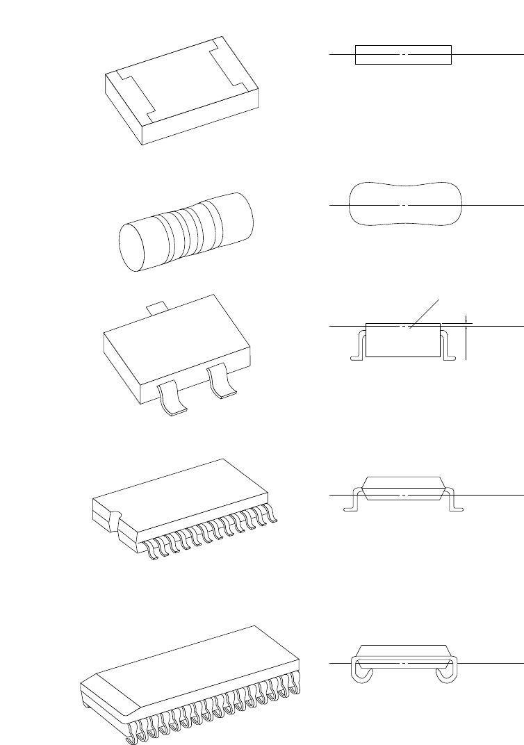
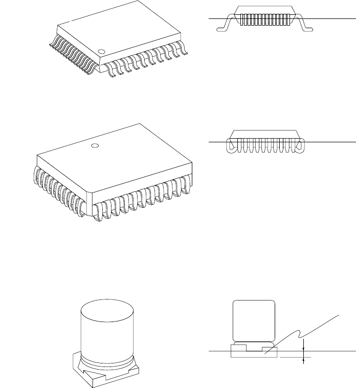
(2) Laser align measurement position for major component types
* See “Setting of the Expanded Window” of Section 5.5 “Component Data”.
0.25
Figure 1.1.2.3
S
q
uare chi
p
MELF
SOT
SOP/TSOP
SOJ
(Center between the top and
bottom surfaces of the
component)
(Center of the component)
(0.25 mm above the top of the component)
Mold
(Center between the bottom surface of
the component and the foot of the leads)
(Center between the bottom surface of
the component and the foot of the leads)
Laser align
measurement position
Laser align
measurement position
Laser align
measurement position
Laser align
measurement position
Laser align
measurement position
1 − 5
0.45
Figure 1.1.2.4
OFP/BQFP
PLCC
Electrolytic capacitor
(Between the bottom surface of the
mold and the foot of the leads)
Laser align
measurement position
(Between the bottom surface of the
mold and the foot of the leads)
(0.45 mm from the bottom surface of the mold)
Mold
Laser align
measurement position
Laser align
measurement position
1 − 6
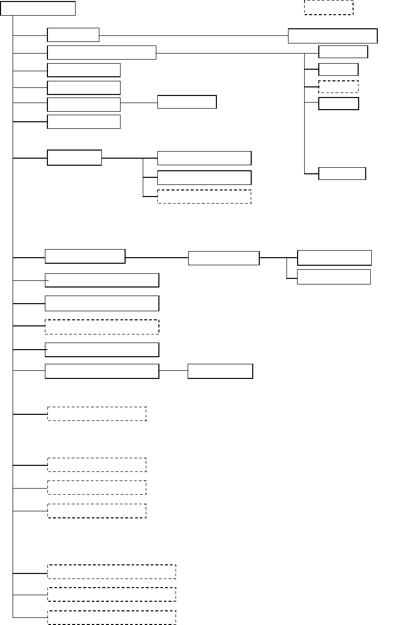
1.1.3 System configuration
1.1.3.1
CRT display
Keyboard
Track ball
FDD
Area sensor
Signal tower
Emergency stop button
Placing head
Automatic tool changer (ATC)
Feeder float detecting function
Pneumatic piping system
Vision Centering System (VCS)
Feeder bank driver
Vision monitor
PWB conveyor unit
Placement station
Tape feeder
Stick feeder
Matrix tray holder
Power unit
CPU board (Flash memory)
I/O control CPU
Motor control unit
Cabinet
X-Y positioning unit
Bulk feeder
KJ-01
Optional
Calibration block (Maintenance tool)
External Programming Unit (EPU)
Pin reference
Shape clamp
Laser recognition head
Bad mark reader
Offset correction camera
M sizes board correspond