KJ-01.02.Instruction Manual.REV.02.pdf - 第147页
5 − 51 − W hen [2/VCS] is selected Figure 5.5.1.9 Screen after [2 / VCS] has been selected ⑤ Component dim ensions Ent er the com ponent width, lengt h, and height using t he for mula bar . W i dth of the com ponent is d…
5 − 50
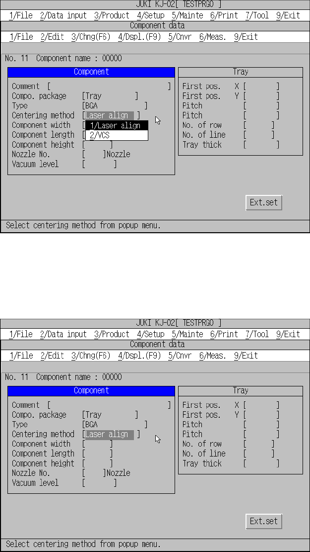
Figure 5.5.1.7 Centering method setting screen
− When [1/Laser align] is selected
Figure 5.5.1.8 Screen displayed after you select “Laser align”
5 − 51
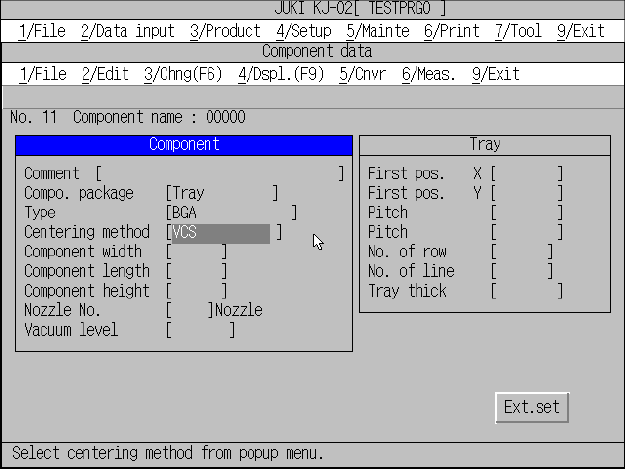
− When [2/VCS] is selected
Figure 5.5.1.9 Screen after [2
/
VCS] has been selected
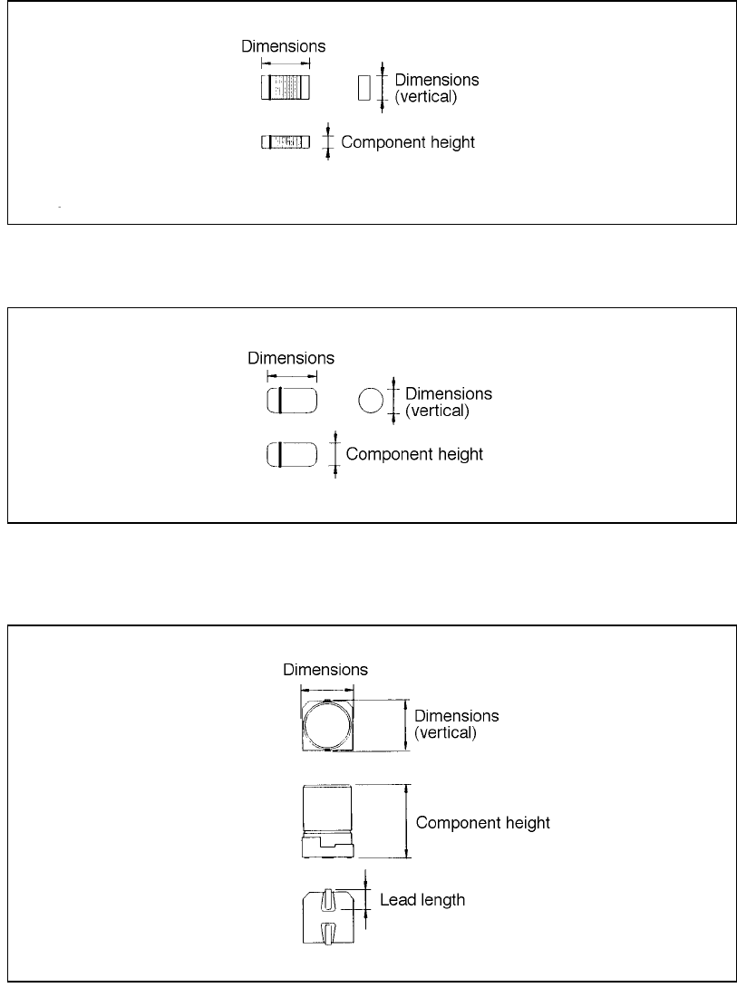
⑤ Component dimensions
Enter the component width, length, and height using the formula bar.
Width of the component is defined in X direction with the placement angle set to
0 degree. Depth of the component is defined in Y direction with the placement
angle set to 0 degree in the same manner. For the outside dimensions, enter the
size at the laser align measurement position (see 1.1.2 “Centering system”).
The following shows the component types and shape of the components.
5 − 52
Examples of component dimensions
See the following examples when you create Component data.
• Square chip
• MELF
• Aluminum electrolytic capacitor
(horizontal)
(horizontal)
(horizontal)
(This dimension does not
include the length of a lead.)