KJ-01.02.Instruction Manual.REV.02.pdf - 第46页
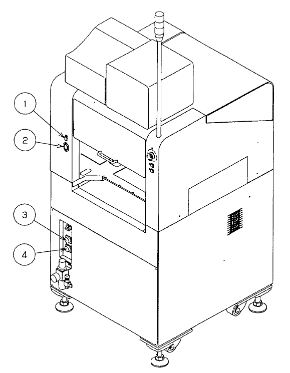
1 − 30 1.4 Interface With Extenal Devices (1) ① is a 15-pin connect or f or a CRT . (2) ② is a 3-pin power connector for a CRT (100V AC). (3) ③ is a 14-pin READY I N connector , and 4 is the 14-pin READY O UT connector :…
1 − 29
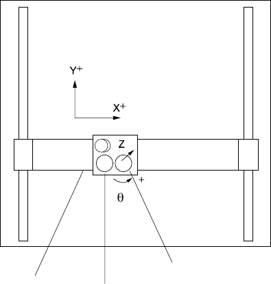
1.3 X, Y, and Z Axes Descriptions
The following four axes (X, Y, Z, and θ) are numerically controlled in this machine.
(1) X- and Y-axis
The X-axis and Y-axis represent the position of the head, OCC, HMS (Height
measurement system), and bad mark sensor. The coordinates of a position are
given as X = ○○○.○○ mm and Y = ○○○.○○ mm, in 0.01-mm increments.
Two coordinate systems are available: software coordinates and tooling-pin (hole
reference) coordinates. Software coordinates mainly show the pickup position
taught in the teach mode, while tooling-pin coordinates represent the placement
position.
(2) Z-axis
The Z-axis represents the position of the nozzle in the head, given as Z = ○○.○○
mm, in 0.01-mm increments. The upward direction is positive (+), with the position
of the nozzle tip on the board being 0.
(3) θ-axis
The θ -axis represents the angle for centering of the head “A = ○○.○○ .” (in 0.05
increments.) The value is positive for counterclockwise rotation and negative for
clockwise rotation.
Figure 1.3.1
X axis
Y axis
Head unit
Bad mark sensor
OCC
1 − 30
1.4 Interface With Extenal Devices
(1) ① is a 15-pin connector for a CRT.
(2) ② is a 3-pin power connector for a CRT (100V AC).
(3) ③ is a 14-pin READY IN connector, and 4 is the 14-pin READY OUT connector:
both are to be used when the machine is configured with other equipment in an
on-line environment.
Figure 1.4.1
1 − 31
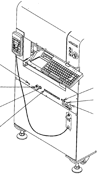
(4) ⑤ is a DSUB 25-pin connector for a printer conforming to the Centeronics
Interface standards.
(5) ⑥ is a connector for an optional trackball.
(6) ⑦ is a connector for a keyboard.
(7) ⑧ is an air coupling for a CAL block.
(8) ⑨ is a female union for a 32-mm adhesive tape feeder.
(9) ⑩ is a 6-pin ALARM signal connector for an optional IC trash belt.
(10) ⑪ is a 12-pin power connector for an optional IC trash belt or 32-mm adhesive
paper tape feeder. Eight connectors of the same type are located on the front of
the machine.
Figure 1.4.2
⑧
⑨
⑩
⑪
⑤
⑥
⑦