KJ-01.02.Instruction Manual.REV.02.pdf - 第224页
6 − 20 ⑩ OK butto n T his butt on allows you to set the method f or r ecognizing a BGA/FBGA/ connector/ outline-to- be-recog nized component (you cannot set t he recognit ion method f or other components). See t he f oll…
6 − 19
⑧ Bot., R, Top and L (Number of leads)
Enter the number of leads.
If the item appears with asterisk (*), it is not necessary to enter any value for that
item.
⑨ Miss1 to 3, Miss1 to Miss3, Bottom, Right, Top and Left
The omitted leads are designated by the number of missing leads and their
positions.
Up to 3 blocks of omitted leads can be set per one side. When there is no
omitted leads, set 0/0.
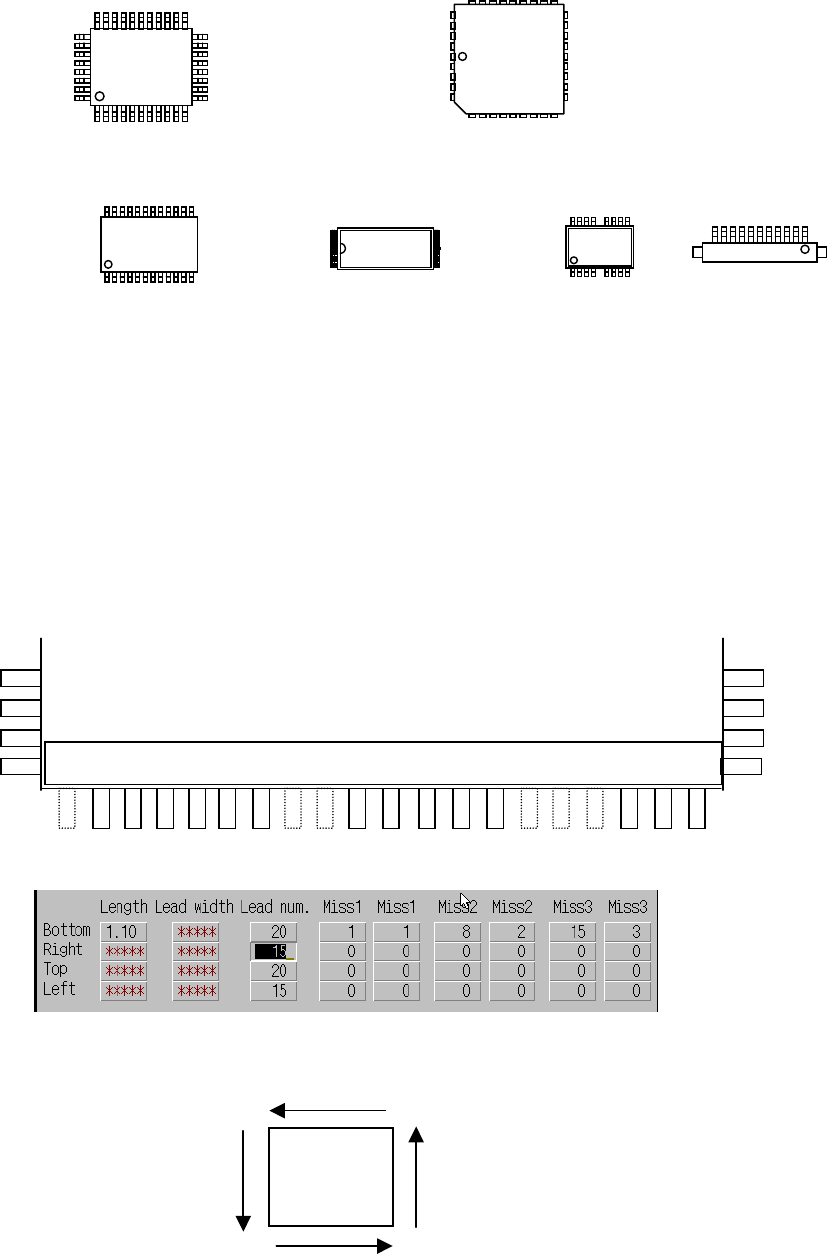
Figure 6.2.3.5 shows the settings when there are omitted leads at the bottom of
the QFP.
<Example> When pins 1, 8, 9, 15, 16, and 17 at the bottom are omitted
Figure 6.2.3.5 Example of lead setting
– Figure 6.2.3.6 shows the order to count the pin numbers.
Figure 6.2.3.6 Counting direction for pin numbers at each side
Top
Left
Bottom
1
Right
Top
Left
Bottom
Right
1
Top
Bottom
1
Left
Right
Top Top
1
1
1 2 3 4 5 6 7 8 9 10 11 12 13 14 15 16 17 18 19 20
Enlarged bottom view of QFP
1 pin from pin 1. 2 pins from pin 8. 3 pins from pin 15.
1
1
1
1
6 − 20
⑩ OK button
This button allows you to set the method for recognizing a
BGA/FBGA/connector/outline-to-be-recognized component (you cannot set the
recognition method for other components).
See the following sections for details of the recognition methods:
For a connector See Section 6.3.
For an outline-to-be-recognized component See Section 6.4.
For a GBA/FBGA See Section 6.5.
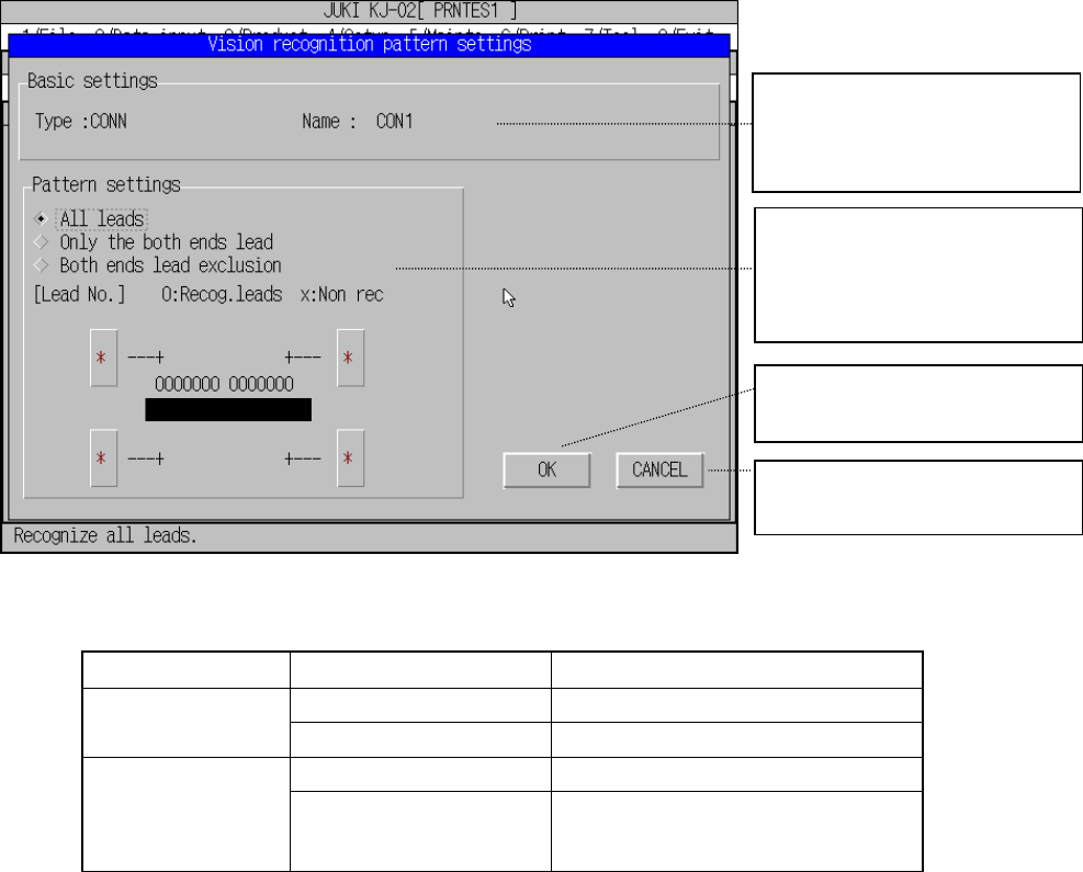
6.3 Setting the Vision Recognition Pattern for a Connector
Set the parameter for a recognition pattern of a unidirectional lead
connector/bi-directional connector/Z-lead connector.
See Table 6.3.2 for displayed data.
Figure 6.3.1 Connector vision recognition pattern settings dialog box
Display group Parameter Description
Type Component type Basic settings
Component name Component name
Pattern settings Specify the lead recognition method. Pattern settings
Lead No. Number of leads to be
recognized/leads not to be recognized
at each corner
Table 6.3.2 Displayed data for setting the vision recognition pattern
Basic settings
Display the basic settings of the
recognition data. This data
cannot be changed.
Pattern settings
Select the lead recognition
pattern here.
Specify the number of leads
when nesessary
Validates your settings, then
closes this dialog box
Cancels your settings, then
closes this dialog box.
6 − 21
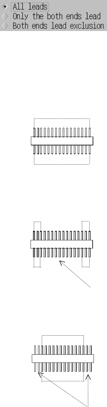
(1) Recognition pattern
1) Selecting the lead recognition pattern
Select a pattern with the radio box.
Note: When you change the recognition pattern with clicking the radio button,
the number of leads is initialized (to the minimum value).
2) Meaning and image of each lead recognition pattern
• All leads: All leads are to be recognized.
• Only the both ends lead: Only leads located on both sides are to be
recognized.
• Both ends lead exclusion: Leads except the specified leads located on
both sides are to be recognized.
Recognized
Recognized
Recognized Recognized
Recognized Recognized
The leads located at the inside are not recognized.
The leads located on the outside are not recognized.
Recognized