KJ-01.02.Instruction Manual.REV.02.pdf - 第194页
5 − 98 5.7.1.3 O peration mode The f igure below shows the mode transit ion in the operation m ode. The [Meas.] comm and can be selected on the Component data edit scr een only . Note 1: Set ting is not stored as t he “P…
5 − 97
5.7.1.2.2 Other functions
(1) Functions
– Changing the pick position
The pick position can be entered manually or with the teaching operation.
Note: The components fed with a tray cannot be stored as the Pick data.
– Recognition center offset
If you enter the offset from the nozzle pick-up position to the component
recognition center at the menu item “Recog. offset” on the Component data
screen, and select “VCS” as the centering method (the component
dimensions and lead information are obtained), the machine recognizes the
component with taking the offset into consideration.
It the nozzle cannot move to the specified coordinates due to the
recognition center offset you set, the machine automatically reverses the
measurement angle to measure the component.
5 − 98
5.7.1.3 Operation mode
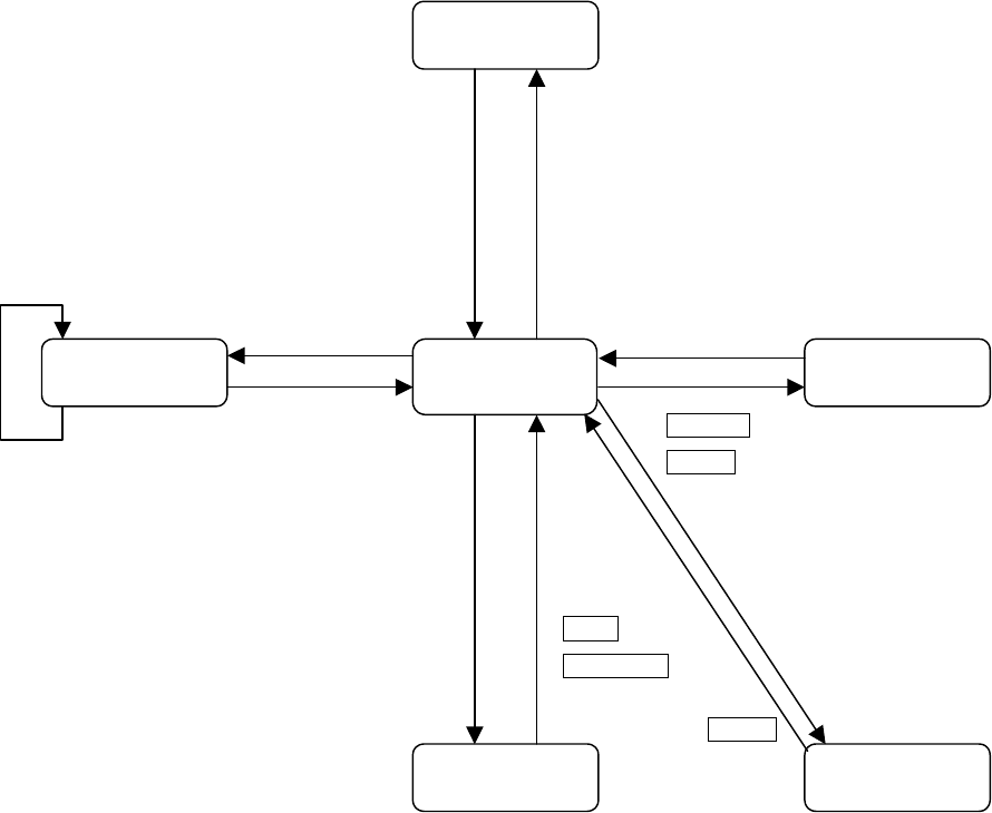
The figure below shows the mode transition in the operation mode.
The [Meas.] command can be selected on the Component data edit screen only.
Note 1: Setting is not stored as the “Pick data”.
Note 2: Mark * shows the timing when the data is stored into the component data
or pick data.
Note 3: Some components are to be returned to the pick position, and the others to
be scrapped.
Note 4: Only when you check the check box “Reflects to the pick data” and change
the component pick-up position, the machine asks you whether to store the
changed data to Pick data
Figure of operation mode transition
Measurement
conditions setting
Pick point change
Measurement
result display
Teaching
Menu selection
Manual input
1 point
measurement
completed
Remeasurement
button, F10
Clicking the <MEAS>
button or pressing the
F10 key.
Move
*
NEXT
、
F5
PREVIOUS、F6
Note 4
Keyboard input
Device key of the HOD
CANCEL
*ENTER Note 1
Moving to the Pick point
* OK button (Note 4)
Moving to the waiting position
Cancel button
Moving to the waiting position
*
ENTER
Note 1
* OK button
Cancel button
Component return
(Note 3)
5 − 99
5.7.2 Components measurement
5.7.2.1 Measurement operations
(1) How to execute measurement
− When you select the [6/Meas.] command on the Component data screen,
and then the [1/Single measurement] command on the displayed menu, the
“Measurement” conditions setting screen appears.
− The machine measures the items whose check boxes are checked.
− You can select two or more items if they are enabled. The enabled items
vary depending on the component type you selected.
(2) Overview of the operation
− When you select the [6/Meas.] command on the Component data screen,
and then the [1/Single measurement] command on the displayed menu, the
“Measurement” conditions setting screen appears.
Notes:
−
−−
−
This function cannot work if both Pick data and Component data
are completely entered.
−
When you click the <MEAS> button, the nozzle moves to the
component pick-up position based on the OCC as the reference
position.
−
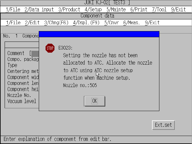
If a nozzle set on Component data is not allocated to the ATC,
the following screen appears.
No nozzle error confirmation screen
Change the current nozzle to a nozzle that is allocated to the ATC on the
Component data, or allocate the current nozzle to the ATC on the
Component data, and select it again.