KJ-01.02.Instruction Manual.REV.02.pdf - 第228页
6 − 24 6.4.2 Limitation on components depending on the recognition method (1) Corn er recognition Recognition condit ions: ① Components whose w hole shape is a regular square or rectang le ② Components whose corner angle…
6 − 23
6.4 Setting the Vision Recognition Pattern for an
Outline-To-Be-Recognized Component
6.4.1 Setting the vision recognition pattern
Set the parameter for the recognition pattern of an outline-to-be-recognized
component.
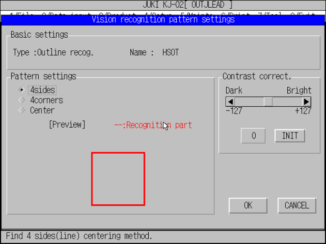
Figure 6.4.1.1 Outline-to-be-recognized component vision
recognition pattern settings dialog box
(1) Setting the recognition pattern
Set the pattern for recognizing an outline-to-be-recognized component with the
VCS.
When you set the recognition pattern, the machine previews it.
Click the radio button corresponding to the desired recognition method.
1) 4sides
Recognizes a component with four sides (straight lines) of a rectangle.
2) 4corners
Recognizes a component with four corners of a rectangle.
3) Center
Requires the center and moment of an object.
(2) Contrast correct.
Set the threshold for correcting the contrast obtained when a component is
recognized.
Use the scroll bar or enter a value in the edit box to set the threshold. This
value corrects the contrast level of the recognized image of a component to
judge the recognition result more strictly or more tolerantly.
When you click the <INIT> button, the threshold is set to the default value (= 0).
6 − 24
6.4.2 Limitation on components depending on the recognition method
(1) Corner recognition
Recognition conditions:
① Components whose whole shape is a regular square or rectangle
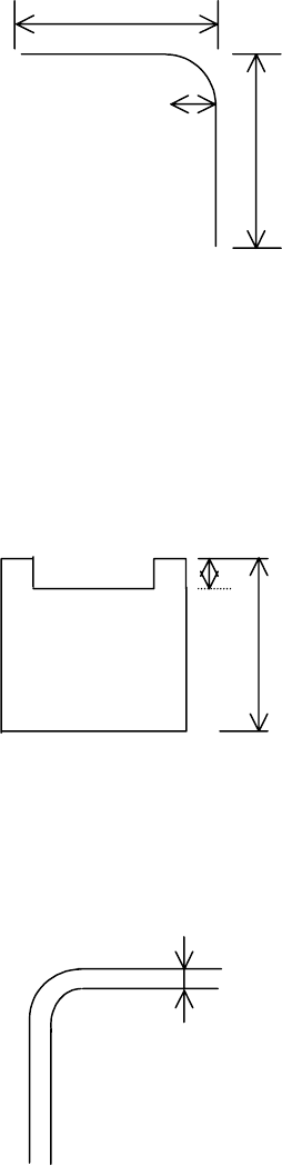
② Components whose corner angle R is 0.5 mm or less
③ Components whose linear portion length forming each side is 2 mm or more
Fig. 6.4.2.1 Explanatory Drawing of Recognition Conditions ②
②②
② and ③
③③
③
④ Components whose 4 corner points are at vertexes of a regular square or
rectangle
⑤ Components whose outline is not convex
⑥ Components with concave portions whose L1 is 10% or less of L2
Fig. 6.4.2.2 Explanatory Drawing of Recognition Condition ⑥
⑦ Components whose sides are 0.3 mm or more when their insides are imaged
darkly at imaging
Fig. 6.4.2.3 Explanatory Drawing of Recognition Condition ⑦
⑦⑦
⑦
2.00mm
2.00mm
0.5mm
0.3 mm or more
L1
L2
6 − 25
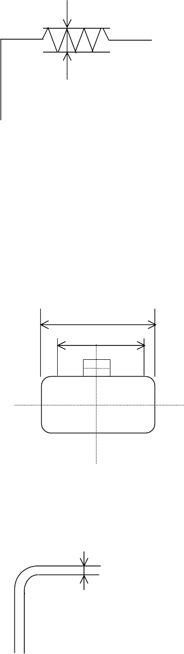
⑧ Components whose side roughness forming a linear portion is 0.1 mm or
less
Fig. 6.4.2.4 Explanatory Drawing of Recognition Condition ⑧
When the above recognition conditions are satisfied, corner recognition is enabled.
(2) Side recognition
① Components whose whole shape is a rectangle or regular square
② Components whose linear portion (line segment) of a side is 1/2 or more of
the component outline size but whose linear portion (line segment) should be
3 mm or more
③ Components whose sides are 0.3 mm or more when their insides are
imaged darkly at imaging
Fig. 6.4.2.5 Explanatory Drawing of Recognition Conditions ①
①①
①, ②
②②
② and ③
③③
③
④ Components whose component angle is within 90± 0.5.
⑤ Components whose sides are 0.3 mm or more when their insides are
imaged darkly at imaging
Fig. 6.4.2.6 Explanatory Drawing of Recognition Condition ⑤
⑤⑤
⑤
0.1 mm or less
Component outline size
Line segment
1.5mm
1.5mm
0.3 mm or more