KJ-01.02.Instruction Manual.REV.02.pdf - 第181页
5 − 85 5.6.5 Tray component data entry (1) T ype Since only a tr ay holder can be installed on the machine, you cannot select its type. (2) Side and No Since a t ray holder is f ixed on the rear side, you cannot enter an…
5 − 84
5.6.4 Stick feeder specifications
- The stick feeder type and the hole positions occupied to install a stick feeder
Table 5.6.4.1
Stick feeder type Number of the hole position
occupied to install a stick feeder
TYPE-N 3
TYPE-W 6
(1) Type
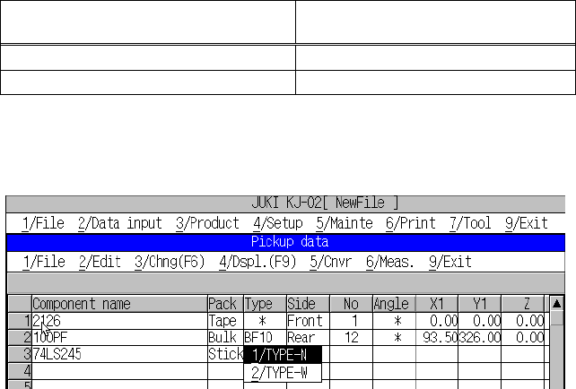
The type of the stick feeder is selected from the pop-up menu.
Figure 5.6.4.1 Stick feeder “Type” setting screen
(2) Side (Supply)
The same as the tape.
(3) No (Position)
This parameter sets the feeder mounting hole number into which the stick feeder
positioning pin is inserted.
When a number is changed, the parameters to the right of “No” are initialized.
As soon as a number is entered, overlap is checked for the existing tape feeders
and tray holders. If the same number already exists, the entry is rejected with an
error message shown on the screen.
(4) Angle
Set the angle for supplying a component.
The item “Angle” indicates the component supply angle based on the placement
angle, 0 degrees.
Since a tape component supply direction should be specified on the Component
data screen, you cannot specify its supply angle. The anti-clockwise direction is
supposed to be positive.
(5) X1, Y1, Z
These parameters set the coordinates of the feeder suction position. When
“Sply”, “Pos.”, “Type”, and “Lane” are set, these values are automatically
calculated and shown.
Fine-adjustments are possible by teaching.
(6) Use
The same as the tape.
5 − 85
5.6.5 Tray component data entry
(1) Type
Since only a tray holder can be installed on the machine, you cannot select its
type.
(2) Side and No
Since a tray holder is fixed on the rear side, you cannot enter any type or
number.
(3) Angle
See the description of a tape feeder also.
When you enter a value to this item, the machine checks to see if the position of
a tray holder is not overlapped with another device: the already set tape feeder,
stick feeder and/or bulk feeder. If it is overlapped, an error message appears
on the screen, and the machine rejects your setting of the item “Angle.”
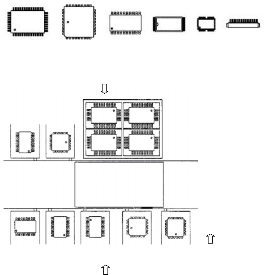
− Placement angle 0°
QFP QFP (PLCC) SOP TSOP-1 TSOP-2 Connector
Figure 5.6.5.1 Placement angle
0
00
0°
°°
°
− Setting example of supply angle
Figure 5.6.5.2 Supply angle of components
Tray holder
QFP
0°
Stick feeder
QFP
0°
SOP
270°
SOP
0°
SOP
90°
SOP
270°
QFJ
0°
QFJ
90°
Figure of stick feeder
at the front side of the machine
: Direction of the view which
is used for determining the
"Supply angle"
5 − 86
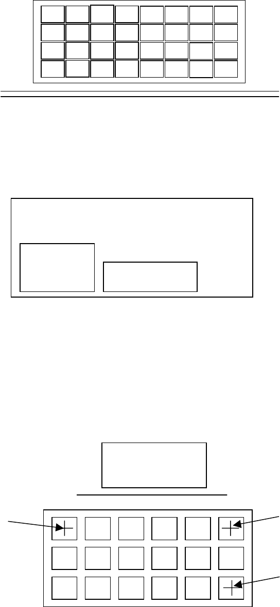
− Order for picking up a component from a tray holder
Figure 5.6.5.3 Order for picking up a component from a tray holder
− Trays are arranged inside a tray holder as shown below.
Up to five trays can be set in a tray holder.
(4) X1, Y1, Z, X2, Y2, X3, Y3
Enter component-picking-up positions at three corners of a tray.
When you enter (X1, Y1) first, (X2, Y2) and (X3, Y3) are entered (or taught)
automatically based on the tray information specified on the Component data
screen.
Once a value is entered, you can change (or teach) each point.
Rear
Figure 5.6.5.2 Coordinates indicating component pick-up positions on a tray holder
1
2
3
4
5
6
7
8
9
Transport path
Tray holder
Tray 1
Tray 2
PWB
(X1,Y1)
(X2,Y2)
(X3,Y3)