KJ-01.02.Instruction Manual.REV.02.pdf - 第111页
5 − 15 (4) BOC ty pe 1) Not used Product ion is carried out not using the BO C mark . (T he mark printed on t he PW B and to be used for off setting the placement point. See 5. Board Recognition Mark s of 1. 1.7 Printed …
5 − 14
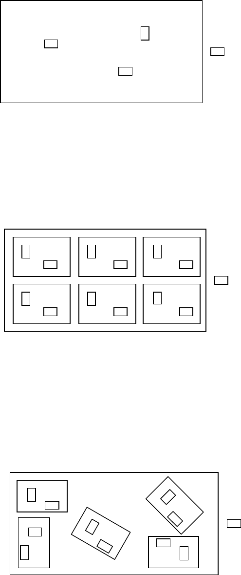
(3) PWB configuration
1) Single PWB
The PWB which has only one circuit pattern.
Figure 5.3.2.4 Figure of the single pattern
2) Multiple PWB matrix
The PWB which has multiple circuit patterns aligned in depth and width and
with a same angle and space.
Figure 5.3.2.5 Figure of the Matrix multiple patterns
3) Multiple PWB non-matrix
The PWB which has multiple circuit patterns but with a different angle and
space among them.
Figure 5.3.2.6 Figure of the Non-matrix multiple patterns
Components
Components
Components
5 − 15
(4) BOC type
1) Not used
Production is carried out not using the BOC mark. (The mark printed on the
PWB and to be used for offsetting the placement point. See 5. Board
Recognition Marks of 1.1.7 Printed circuit board specifications.)
2) PWB mark is used
A set of BOC marks are used for the placement point offset of the entire
PWB area. When the BOC mark is used for a single pattern PWB, select
this item. When a set of BOC marks is used for the entire area of a multi
pattern PWB, select also this item.
3) Circuit mark is used
For a multiple pattern PWB, when the BOC mark of each pattern is used for
the placement point offset of each circuit of the PWB, select this item.
Accuracy of placement is better compared with the placement using the
BOC
(5) Bad mark type
1) Not used
Select this item when production is carried out without using bad marks.
(The bad marks are used for recognizing a certain circuit of a multiple
pattern PWB where components are not to be mounted. Normally, sealing or
painting is applied for the bad marks.) For a single pattern PWB, the bad
marks cannot be used, and select this item.
2) Mark is light
Select this item when a bad mark and the PWB are recognized with the bad
mark sensor, and the reflection ratio of the bad mark is higher than that of
the PWB.
3) Mark is dark
Select this item when a bad mark and the PWB are recognized with the bad
mark sensor, and the reflection ratio of the bad mark is lower than that of the
PWB. This item shall be selected particularly when black bad marks are
used on a ceramic board.
5 − 16
5.3.3 Configuration set up
When selecting the <CONFIG.> button in the basic setup window, the [Configuration
set up] window appears. For dimension setting, settings of <Circuit> and <BOC mark
position> differ among PWB types, such as single pattern, matrix multiple patterns,
and non-matrix multiple patterns, which are designated as <PWB configuration> in
the [Basic set up] window.
(1) Single PWB (single-plane PWB)
1) PWB Reference
Set the distance from the PWB home position to the PWB positioning point
(that is, reference pin position when you select “Hole reference” as
“Reference,” or shape reference position when you select “Shape
reference.”
2) BOC mark position
Set the coordinates of the center point of the BOC mark. Specify at least
two positions here. Be sure to enter coordinates viewed from the home
position of a PWB.
3) Vision data
The parentheses ( ) at the right edge of the BOC mark position shows the
completeness of the vision data. When the vision data is complete, an
asterisk * appears in the parentheses ( ). For teaching of the vision data, see
6.3 “Teaching Recognition”.
4) Bad mark position
An asterisk * is indicated because this cannot be selected for a single
pattern PWB.
5) PWB height
Set the height of the top side of a PWB. The height of the top side of a
fixed PWB is regarded as “0.”
If a PWB is placed on the jig board or any other object, be sure to specify
the height of the side on which components are to be placed.
*1 You can use the HOD to teach the home position of a PWB, BOC mark
position and PWB height. See Section 6.2 “Teaching Coordinates” for
details.