KJ-01.02.Instruction Manual.REV.02.pdf - 第294页
8 − 27 <4> Exit W hen the machine produces t he planned number of PW Bs, it displays the “Production conditions” dialog box again. T he signal lig hts indicate t hat the machine is in the product ion waiting condit…
8 − 26
Pick data Placement data
Cause
Position
X, Y Z X, Y Z
Remarks
Pick point
○ ○
User request by the STOP key
Stop of the step operation
The cover is opened.
The area sensor is activated.
Placement
point
○
- Starts from XY teaching
- Effective HOD device keys are
[CAMERA],and [HEAD].
Only the head key is for the head
when put in the pause mode is
effective.
* 1. Teaching of pick point is set in the order of input, and only possible for
sequential pickup.
2. Teaching of pick point for tray components is impossible.
3. Teaching of placement point is possible only during reference circuit pattern
placement, and is not possible for the boards with which a bad mark of
reference circuit pattern is detected.
4. Only the data of TEACH IN item with the lit LED of the HOD immediately
before pressing the [ENTER] key of the HOD is to be set. If you want XY, Z,
and Vac be taught and set, teaching is to be performed separately.
<3> Stop
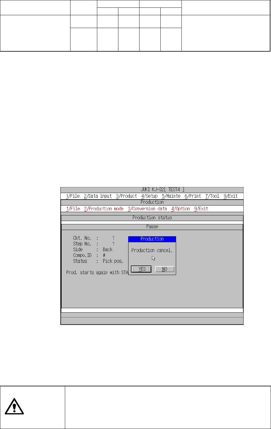
The STOP button is used to stop board production before the preset number of
PC boards are processed. When the STOP button is pressed while the
production temporarily stops, the Figure 8.2.2.4 Stop dialog box appears.
Figure 8.2.2.4 Production stop confirmation dialog box
When you click the <YES> button, the clamped board is released, and the
machine allows you to set the production conditions. When you click the <NO>
button, the machine returns to the condition in which it was before you pressed
the STOP key; the machine enters Pause condition.
CAUTION
Even when the production is stopped, X and Y axes and the head
continue to move to carry out nozzle replacement.
To avoid a risk of injury, do not place your hand in the machine, nor
move your face or head close to the machine when stopping
theproduction.
8 − 27
<4> Exit
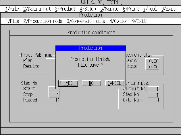
When the machine produces the planned number of PWBs, it displays the
“Production conditions” dialog box again. The signal lights indicate that the
machine is in the production waiting condition, and it produced the planned
number of PWBs.
To exit the production operation, select [9/ Exit] in the menu bar.
The Exit dialog box has radio buttons used to select whether or not to save the
file.
When you click the <YES> button, the machine saves the current production
operation, and quits Production mode.]
When you click the <NO> button, the machine quits Production mode without
saving the current production condition.
When you click the <CANCEL> button, the machine returns to the previous
condition it was before you clicked the [9/Exit] command without quitting
Production mode.
8 − 28
8.2.3 Production management information
In the Continuous and Trial run mode, production management information is stored.
This section explains procedures to display the production management information
that has been stored.
(1) Conditions to create the production management information data
① When the production mode is set for the PWB production and the production
is performed for all placement positions (except when the placement step is
changed).
② Once the production data is created, new data for the next production is
added to the previous data.
If entirely new data is to be created, it is necessary to reset the data
creation.
(2) Items
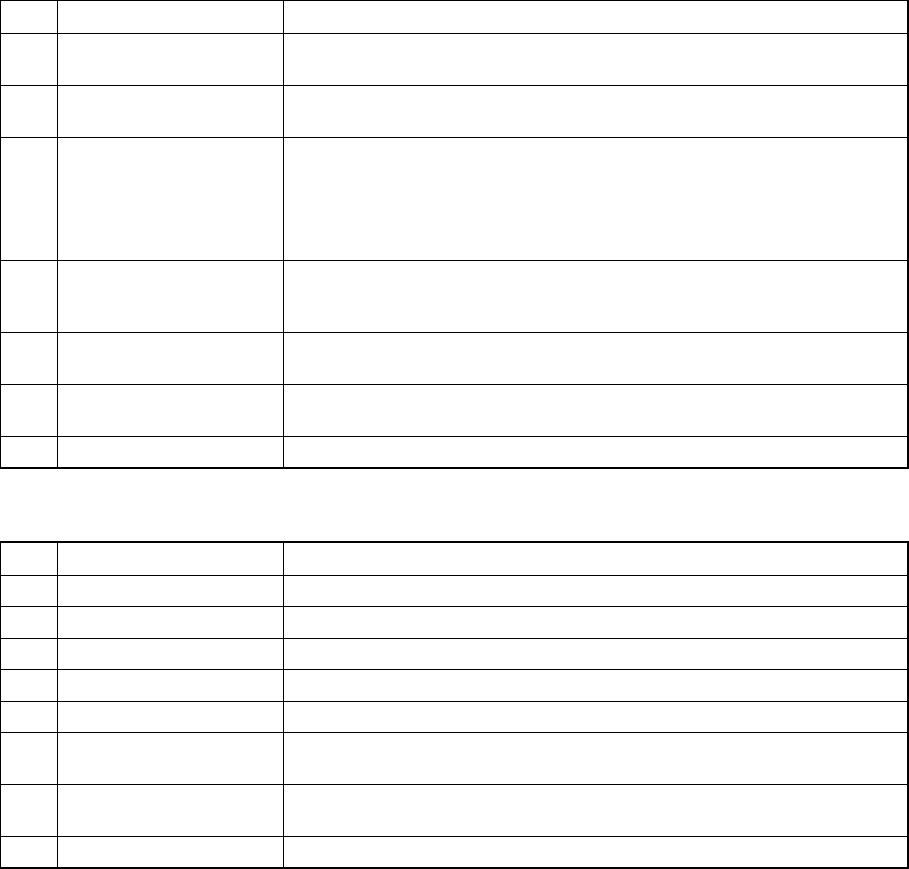
① Total management information
No. Item Description
1 Production PWB number The number of boards produced after production management information
is cleared. (Only for complete boards)
2 Production start time Date and time when the first production is started after after production
management information is cleared.
3 Running time The time duration from when production is started to when the production is
completed excluding any stop time duration. Pause time duration is also
excluded.
Production start time means when the first component is to be picked up.
Production end time means when the last component is placed.
4 Stop time The time duration from when production is started to when the production is
completed including any stop time duration when the production is put in to
halt, emergency stop, etc.
5 Picked component
number
This means the number of successfully picked components.
6 Placed component
number
This means the number of successfully placed components.
7 Detection of No. Bad mark This means the number of circuits whose bad mark is detected.
② Management information on production with the front side, rear side or tray holder
No. Item Description
1 Picked The number of components successfully picked from the feeder.
2 Placed The number of components successfully picked, then placed from the feeder.
3 PickEr.(Pickup error) The number of pickup errors occurred at the feeder.
4 Retry The number of retry over error occurred to the feeder.
5 Recog. (Recognition) Number of laser/VCS recognition retry over errors that occurred at the feeder
6 C Display the centering method: L indicates laser recognition, and V
indicates VCS recognition
7 Chip Number of components that were picked up from the feeder, detected a
tombstone error and discarded.
8 Vlfy (Verify) Unused.