KJ-01.02.Instruction Manual.REV.02.pdf - 第393页
14 − 24 14.4.4 Ball screw s and Linear w ay (Head part) ( KJ-02) Apply a light coating of grease ( C grease) t o the ball screws and the linear way rails. Apply a light coating of g rease ( C grease) t o the spline shaf …
14 − 23
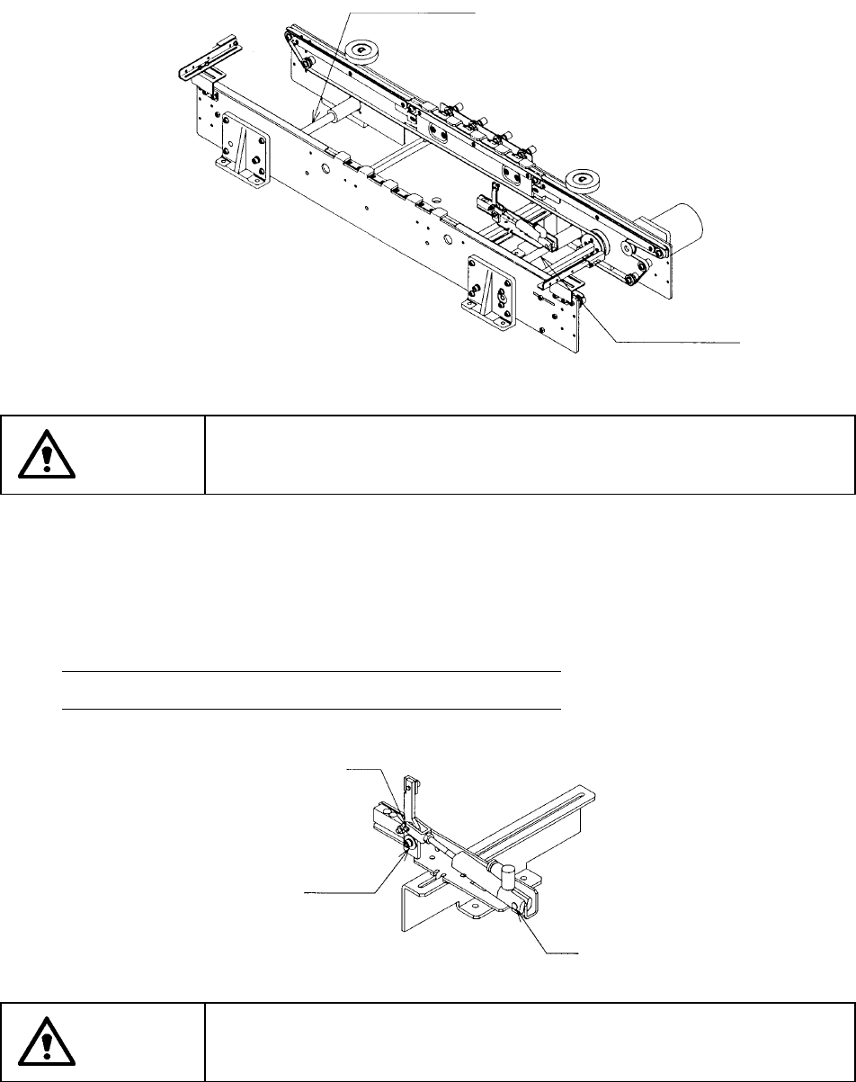
14.4.2 Transport guide shaft
Apply grease to all sides of the guide shafts (two).
WARNING
To prevent the body from injury which can be caused by accidental
activation of the machine, cut off the power to the machine before starting
to work.
14.4.3 PWB stopper part
Apply grease to two axes shown in the figure below.
Note: Do not apply any grease to the bearing.
WARNING
To prevent the body from injury which can be caused by accidental
activation of the machine, cut off the power to the machine before starting
to work.
PWB transport guide shaft
PWB transport guide shaft
Axis A
Bearing
Axis B
14 − 24
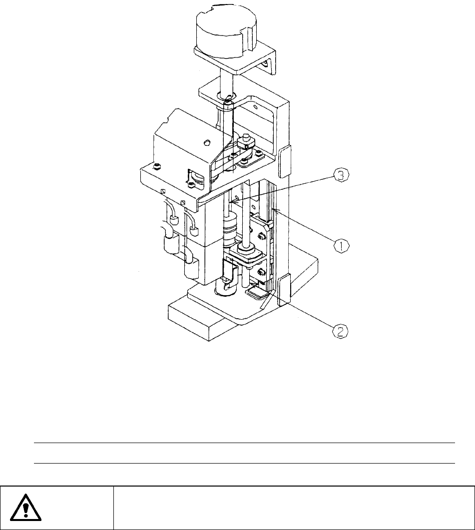
14.4.4 Ball screws and Linear way (Head part) (KJ-02)
Apply a light coating of grease (C grease) to the ball screws and the linear way rails.
Apply a light coating of grease (C grease) to the spline shaft axis.
After applied the grease, move the Z axis by hand for the grease to be fit.
After fitting grease to the spline shaft axis sufficiently, remove extra grease with
cloth or similar matter so that it cannot be splattered.
① Linear way
② Ball screws
③ Spline shaft
Notes: Never apply any grease other than C grease to the parts above.
WARNING
To prevent the body from injury which can be caused by accidental
activation of the machine, cut off the power to the machine before starting
to work.
14 − 25
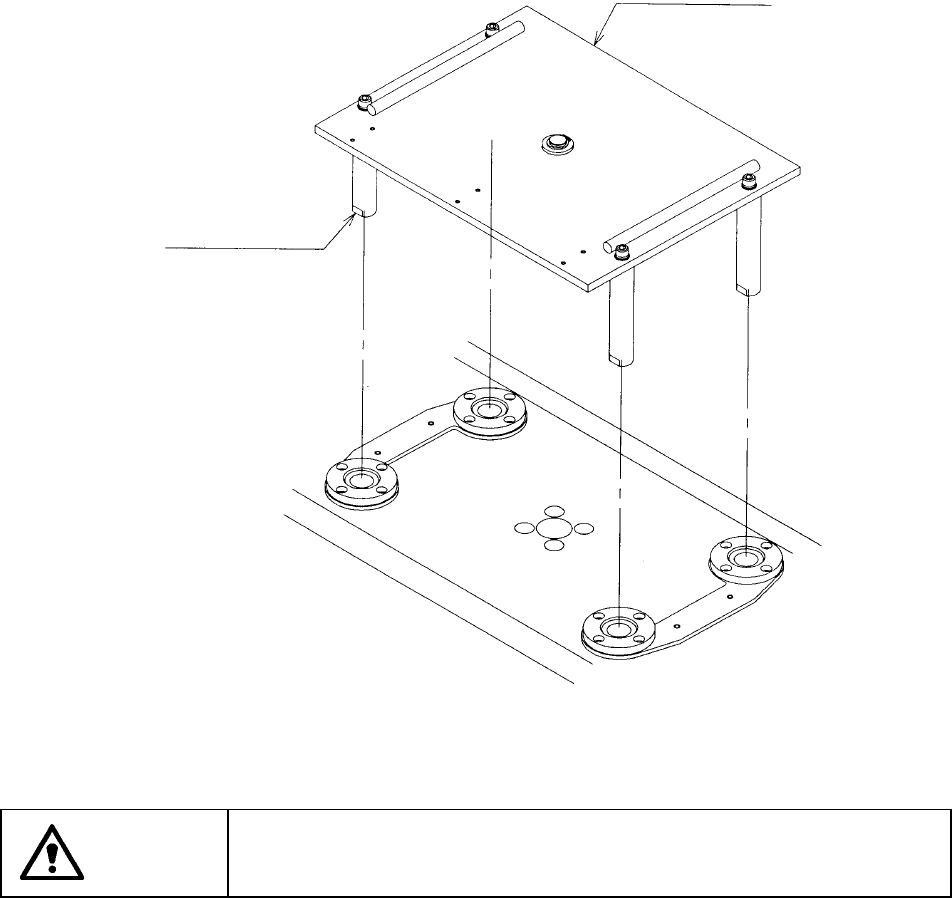
14.4.5 Backup table
Apply grease to the support shafts (four) thoroughly.
Lift up the support table with your hands, and grease it from the both sides.
WARNING
To prevent the body from injury which can be caused by accidental
activation of the machine, cut off the power to the machine before starting
to work.
Support table
Support shaft