KJ-01.02.Instruction Manual.REV.02.pdf - 第71页
3 − 14 (2) Progr am edit local m enu (3) Production local menu 1/File 2/E dit 3/ Chng(F6) 4/Dspl. (F9) 5/Cnvr 6/Meas. 9/Exit 1/Ope n... 2/Save 3/New ... 4/Sav e as... 9/Exit 1/Copy F3 2/Delete F4 3/Move F5 4/Ins ert 5/Du…
3 − 13
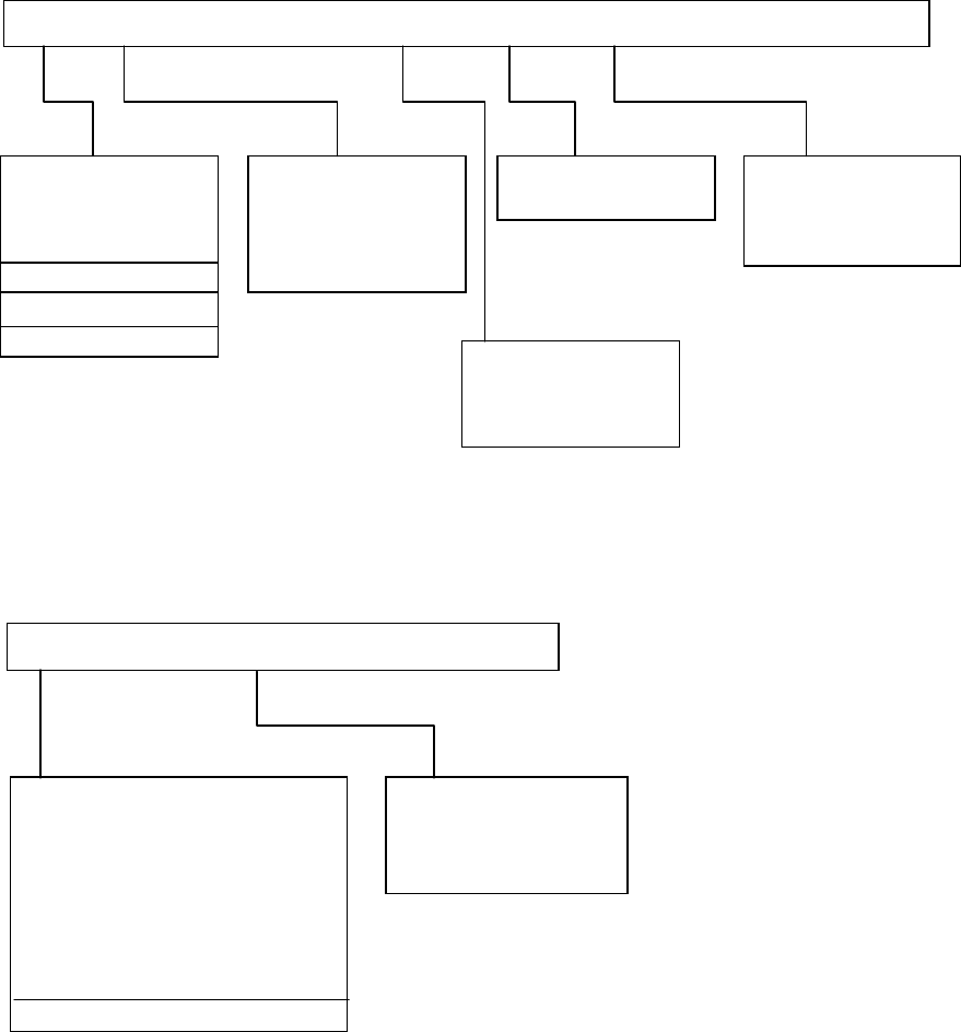
3.3.5 Menu organization
Top menu
* The menu items appeared in red cannot be selected.
Local menu
(1) Machine setup local menu
1/File 2/Data input 3/Product 4/Setup 5/Mainte 6/Print 7/Tool 9/Exit
1/PWD data
2/Placement data
3/Component data
4/Pick data
5/Vision data
1/Warm up
2/Idle mode
1/Data file list
2/Production data
3/Setup
4/Production info
1/Unit...
2/Opn. option...
3/Machine setup...
4/Manual control...
1/Set up group 2/PWB conveyor 9/Exit
1/ATC nozzle setup...
2/Vacuum value without nozzle...
3/Device enable...
4/Reference pin position...
5/Shape clamp position...
6/Component scrap position...
7/Trash conveyor belt position...
8/PWB conveyor...
A/Signal light
9/Exit
1/Initialize
2/Load PWB
3/ Eject PWB
4/ Release clamp
1/Open...
2/Save
3/New...
4/Save as...
5/File maintenance...
9/Exit
A/About program
3 − 14
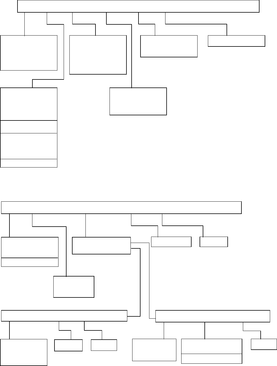
(2) Program edit local menu
(3) Production local menu
1/File 2/Edit 3/Chng(F6) 4/Dspl.(F9) 5/Cnvr 6/Meas. 9/Exit
1/Open...
2/Save
3/New...
4/Save as...
9/Exit
1/Copy F3
2/Delete F4
3/Move F5
4/Insert
5/Duplicate
6/Jump
7/Find
8/Vision copy
9/Nozzle sort
A/Component name
B/Pick point recalc
C/Mark database
1/PWB load
2/PWB eject
3/BOC align
1/PWB data
2/Placement data
3/Component data
4/Pickup data
5/Vision data
6/Data compl. state
1/Component form
2/Component list
3/Pick input
4/Feeder order
1/Current comp.
1/File 2/Production mode 3/Conversion data 4/Option 9/Exit
1/Open...
2/Save
3/Save as...
9/Exit
1/PWB prod.
2/Trial
3/Dry run
9/Exit
1/Parts No. set up
2/Management info.
1/Option
1/Select expression 2/Clear 9/Exit
1/Total
2/Front
3/Rear
4/Tray holder
1/Clear 9/Exit
1/Supply select 2/Parts supply 9/Exit
1/Front
2/Rear
3/Tray holder
1/Replenish component
2/Replenish all feeders
3/Update display
9/Exit
4 − 1
CHAPTER 4 SETUP
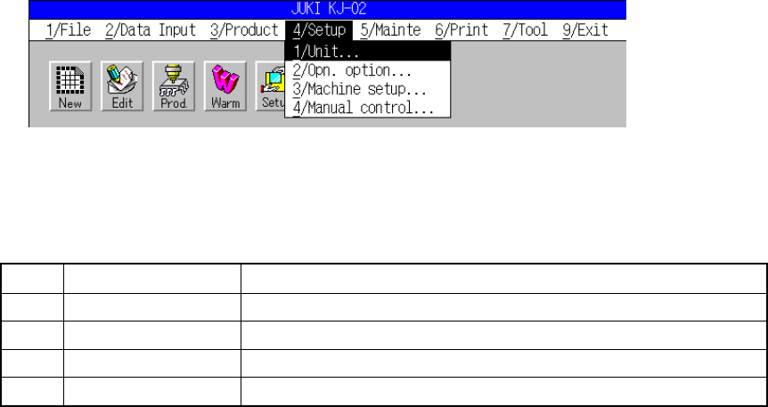
The setup menu screen, as shown in Figure 4.1, appears when [4/ Setup] is selected from
the menu bar.
Figure 4.1 Setup menu screen
Table 4.1 Setup commands
No. Command Characters displayed on the message line
1 Units of measure Sets the unit system for length and pressure.
2 Opn. option Sets the options for operation.
3 Machine setup Sets the machine setup status.
4 Manual control Carries out a test for devices in manual operation.
See CHAPTER 10 “MANUAL CONTROL” for [4/ Manual control].
* The data of the screen shown here are only for your reference and it is for the
machine which is front-reference and right-to-left-transportation type.