KJ-01.02.Instruction Manual.REV.02.pdf - 第41页
1 − 25 1.2.6 Nozzle (1) Select the nozzle from No. 501 throug h No.508, accor ding to t he shape and size of t he components to be m ounted. T able 1.2.6.1 Nozzles f or laser recognition NO. 501 502 503 504 505 506 507 5…
1 − 24
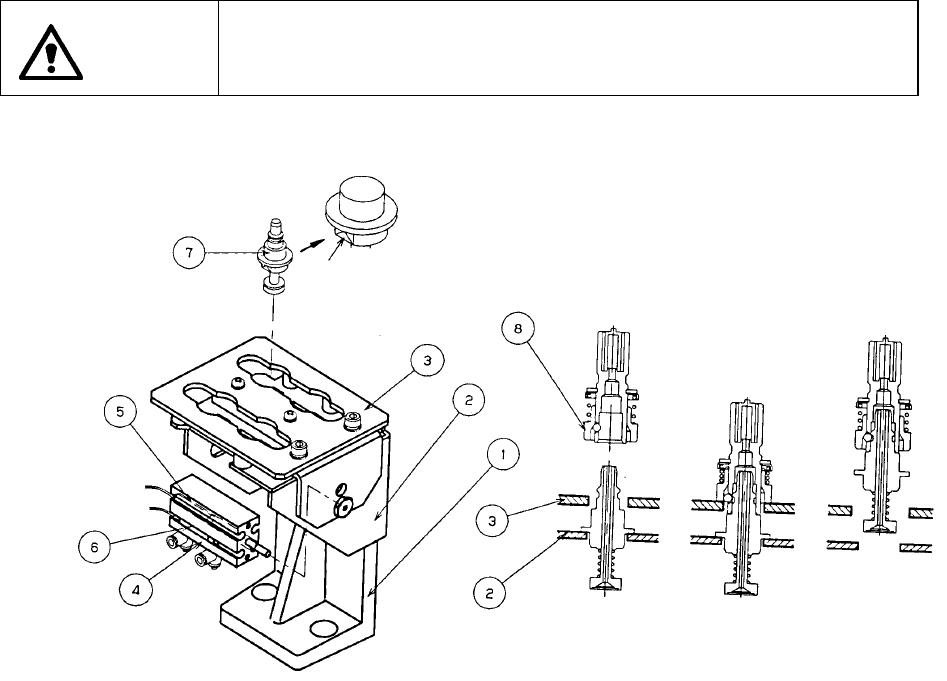
1.2.5 ATC unit (Automatic tool changer): parts identification
The slide plate ③ hooks the nozzle outer ⑧ and removes the nozzle ⑦ with air
supplied from the head unit, and attaches it with air sucked by the head unit. The air
cylinder ④ opens or closes the slide plate ③ to remove out/store the nozzle.
When you have to replace the current nozzle with another one due to changeover of
the feeder, manually push and open the slide plate ③.
WARNING
To prevent injury to the body which can be caused by an accidental
activation of the machine, cut off the power to the machine before
starting nozzle change.
Figure 1.2.5
① ATC mounting base ⑤ ATC OPEN sensor
② ATC base ⑥ ATC CLOSE sensor
③ Slide plate ⑦ Nozzle
④ Air cylinder ⑧ Nozzle outer
Cut side
1 − 25
1.2.6 Nozzle
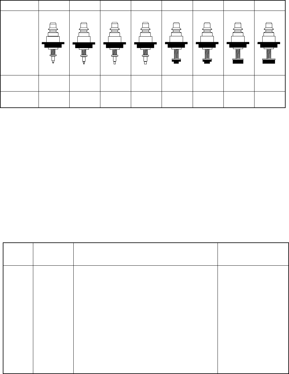
(1) Select the nozzle from No.501 through No.508, according to the shape and size
of the components to be mounted.
Table 1.2.6.1 Nozzles for laser recognition
NO. 501 502 503 504 505 506 507 508
Appearance
Outer
Diameter
0.7x
0.4mm
φ0.7mm φ1.0mm φ1.5mm φ3.5mm φ5.0mm φ8.5mm φ9.5mm
Inner
Diameter
φ0.25 mm φ0.4mm φ0.6mm φ1.0mm φ1.7mm φ3.2mm φ5.0mm φ8.0mm
The machine is equipped with one No. 502 nozzle, one No. 504 nozzle, one No.
506 nozzle and one No. 508 nozzle.
(2) Nozzle selection
The nozzle can be automatically recognized if you follow the explanation of
"3.4.1 ATC Nozzle Selection". If you manually select the nozzle, select the
nozzle with extreme care to prevent poor pickup and placement of a compornent.
The nozzle numbers for major types of components to placed be are shown in
Table 1.2.6.2. However, to keep accuracy of pickup and placement, select the
appropriate nozzle No. by referring to the minimum size of the suction area of
each component.
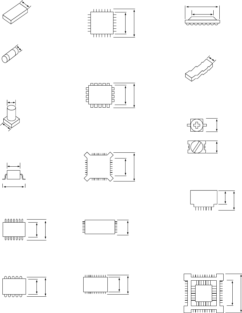
See the item (3) for the minimum width (D) of the sucked area of each
component.
Table 1.2.6.2 Nozzles and their pickable minimum component width
Nozzle
No.
Minimum
component
width (D)
Major types of components
Applicable components
to be placed
501
502
503
504
505
506
507
508
to 0.45
0.45 to 0.75
0.75 to 1.45
1.1 to 2.5
2.5 to 4
4 to 7
7 to 10
10 or more
0603
1005
1608, SOT(Molded part: 1.6 x 0.8),
2012, SOT(Molded part: 2.0 x 1.25)
2012, 3216, SOT(Molded part: 2.0 x 1.25), SOT23,
Aluminum electrolytic capacitor (small),
tantalum capacitor, trimmer
Aluminum electrolytic capacitor (medium),
SOP (narrow type), SOJ
Aluminum electrolytic capacitor (large),
SOP (wide type), TSOP
QFP, PLCC, BGA
3225, tantalum capacitor
1 − 26
(3) Minimum component width (D) of each component.
!1
A
D
A
D
W
D
A
D = A
A
D
A
D
A
D
A
D
D
A
D = A
A
A
A
D = A
AA
D = A
A
D
A
D
A
D
① Square chip
② MELF
③ Aluminum
electrolytic capacitor
D = A + 0.5mm
④ SOT
⑤ SOP
⑥ SOJ
⑦ QFP ⑫ BGA
⑧ PLCC
⑨ BQFP
⑩ TSOP
⑪ TSOP2
⑬ Network resistor
⑭ Trimmer
⑮ One-way lead connector
⑯ Gull wing socket
J lead socket
Socket with bumper