KJ-01.02.Instruction Manual.REV.02.pdf - 第234页
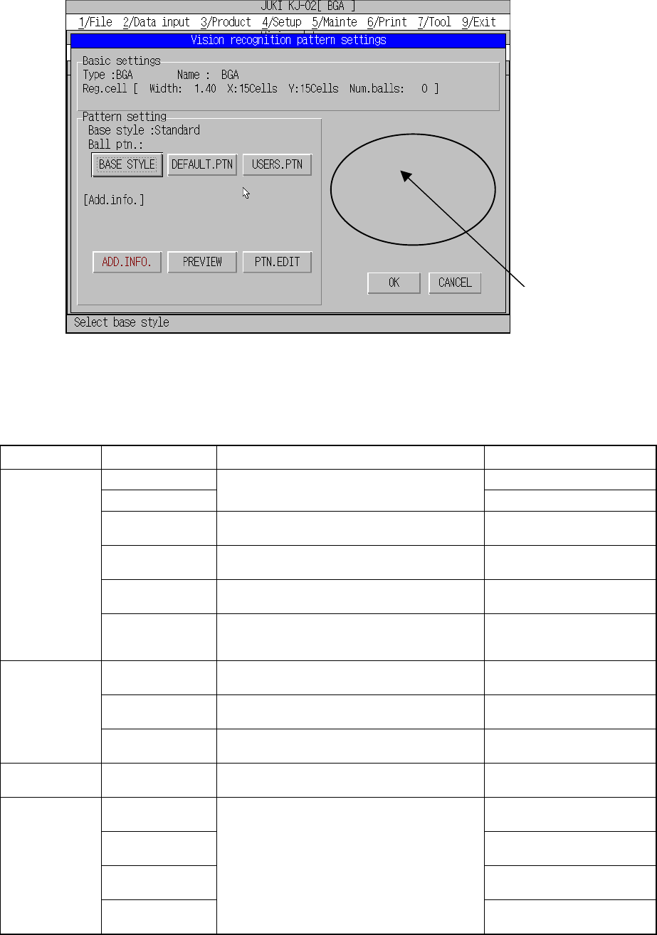
6 − 30 6.5.2 Recognition pattern Set the BGA r ecognit ion patter n as f ollows: The recog nition patt ern consists of the f ollowing patt erns. 1) Base style Using the f ollowing pop-up menu, specify the base st yle inc…
6 − 29
Figure 6.5.1.2 Screen Displayed When “Land” is Selected
Table 6.5.1.1 Displayed data for setting the vision recognition pattern
Display group Parameter Data set by Description
Type Component type
Component name
Component name of the Component data
Component name
Reg. cell width Automatically calculated from the lead pitch and
pattern.
Width of one recognition cell
Reg. cell X Automatically calculated from the number of the
upper and lower leads and pattern.
Number of recognition cells in
the X direction
Reg. cell Y Automatically calculated from the number of the
left and right leads and pattern.
Number of recognition cells in
the Y direction
Basic settings
Num. balls Automatically calculated from the number of the
upper, lower, left and right leads and pattern.
Total number of the recognition
cells where balls are to be
recognized
Base style Base style button Base style name of the BGA
bottom
Ball pattern Default Ptn button Default ball assignment pattern
name
Pattern settings
Users Ptn button User ball assignment pattern
name
Add info. Ball existence lines Set with the Add. info button when “Peripheral
BGA” is selected as the default pattern.
Number of lines where balls are
located on the outer
Diameter Yes = Inspected
No = Not inspected
Diameter inspection
level
Level of the diameter inspection
(1 to 100 %)
Variation Yes = Inspected
No = Not inspected
Ball inspection
Variation inspection
level
Inspection setting button
Level of the odd shape
inspection (1 to 100 %)
You cannot enter
any data for
inspecting a ball.
6 − 30
6.5.2 Recognition pattern
Set the BGA recognition pattern as follows:
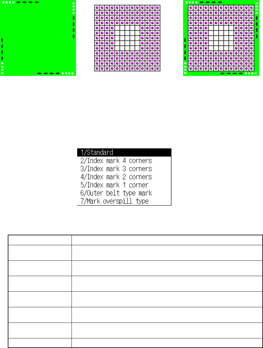
The recognition pattern consists of the following patterns.
1) Base style
Using the following pop-up menu, specify the base style incorporated into the
system as the default.
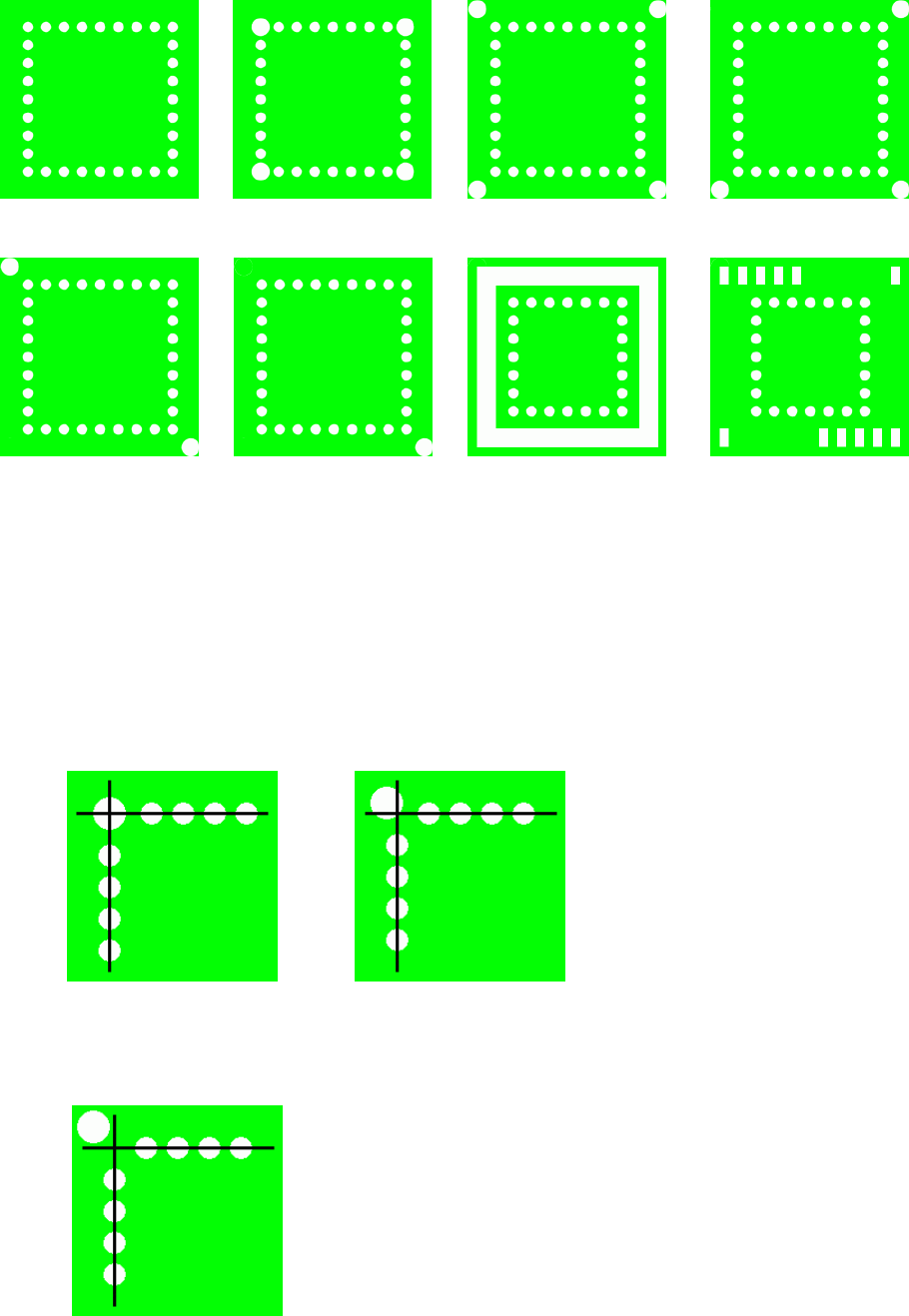
Table 6.5.2.1 Selection conditions of patterns
Style name Descriptions
Standard There are only balls existing on the outer of the package. Index marks are
located on the cross pattern.
Index mark 4 corner There are only balls or index marks existing on the outer of the package, and
index marks are located at four corners as well as on the cross pattern.
Index mark 3 corner There are only balls or index marks existing on the outer of the package, and
index marks are located at three corners as well as on the cross pattern.
Index mark 2 corner There are only balls or index marks existing on the outer of the package, and
index marks are located at two corners as well as on the cross pattern.
Index mark 1 corner There are only balls or index marks existing on the outer of the package, and
index marks are located at one corners as well as on the cross pattern.
Outer belt type mark There are something existing in the shape of a belt whose density is like that
of balls on the outer of the package.
Mark overspil type There are something not a ball on the outer of the package.
*1 An index mark is a mark which indicates a position outside a ball, ball-shaped
partial -pressure of balls, and so on.
+
++
+
=
==
=
Base style Ball pattern
Default pattern
User pattern
Recognition pattern
6 − 31
Default base style sample image
Note 1: The size of an index ball varies from a big one to a small one. In addition,
the center of the index ball is not always aligned with the center of a ball.
Then, to distinguish index marks one to four corner clearly, the index ball
position is set as follows:
When an index ball is on the ball cross pattern, it is handled as the
“Standard” type.
When an index ball is outside the ball cross pattern, it is handled as the
“Index mark one to four corner”.
Standard Index mark 4 corner Index mark 3 corner
Index mark 2 corner Index mark 1 corner Outer belt type mark Mark overspill