KJ-01.02.Instruction Manual.REV.02.pdf - 第103页
5 − 7 Notes − If you load a production progr am created w ith a KE-750 or KE-760 to the m achine, the machine convert s it to t he production progr am in the KJ-02 f ormat : only PWB data, Placement data and Component da…
5 − 6
5.1.7 Exit
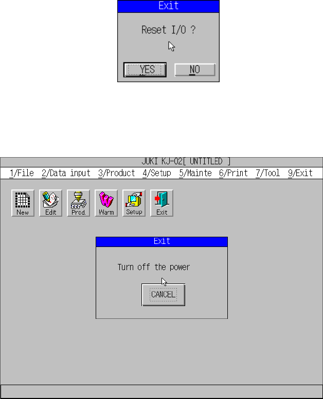
When you select the [Exit] command, the dialog box appears on the screen that asks
you whether to set the safety direction of each I/O device.
When you click the <YES> button, the “Turn off the power” screen appears. Be sure
to turn off the machine only after this screen appears.
5 − 7
Notes
−
If you load a production program created with a KE-750 or KE-760 to the machine,
the machine converts it to the production program in the KJ-02 format: only PWB
data, Placement data and Component data (component names only) of a
production program are converted.
−
Any component name of some KE-750/KE-760 production programs may not be
displayed, or a component name that is not recorded in Placement data may be
displayed.
−
The machine will not convert any production program created with a
KE-750/KE-760 whose version number is earlier than 1.25.
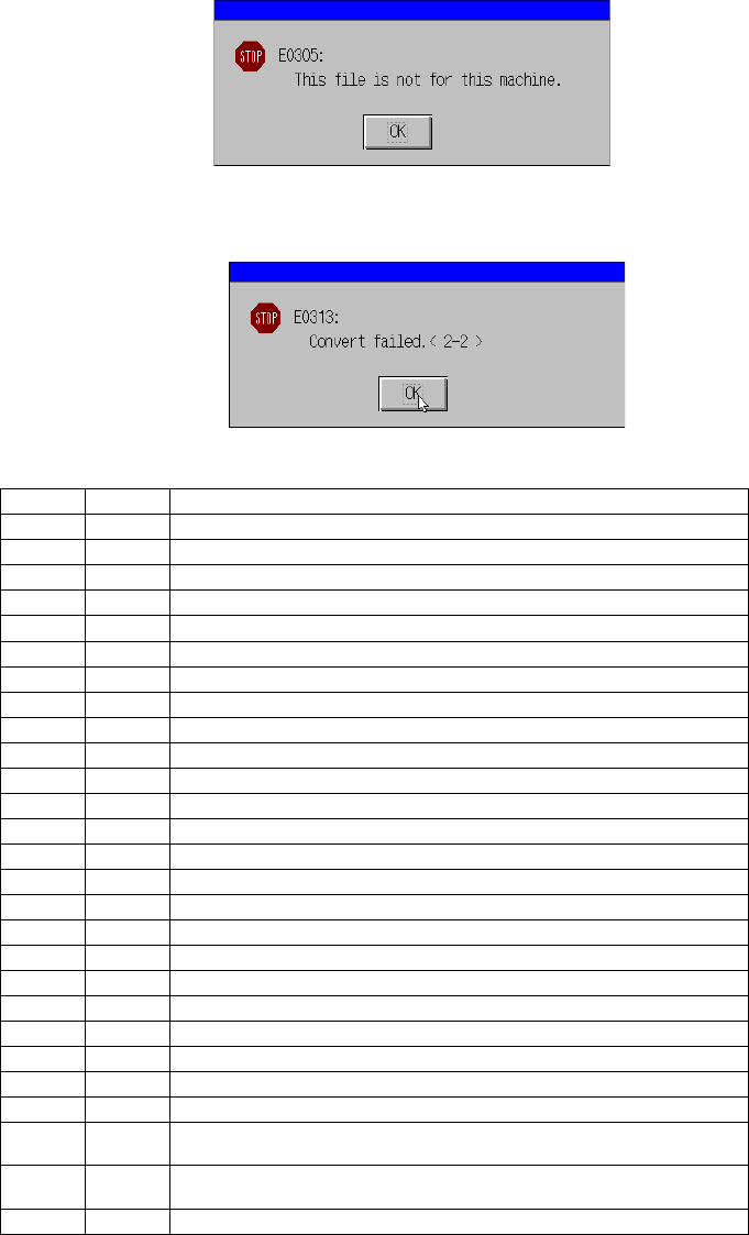
The following error dialog box appears on the screen.
If a conversion error occurs, the following error message appears on the screen,
and the machine stops its data conversion process.
Description of conversion error messages <x-y>
X Y Error description
1 0 PWB data is not complete.
1 1 The PWB home position X is out of the allowable data range.
1 2 The PWB home position X is out of the allowable data range.
1 3 The BOC mark position 1X is out of the allowable data range.
1 4 The BOC mark position 1Y is out of the allowable data range.
1 5 None
1 6 The BOC mark position 2X is out of the allowable data range.
1 7 The BOC mark position 2Y is out of the allowable data range.
1 8 None
1 9 The BOC mark position 3X is out of the allowable data range.
1 10 The BOC mark position 3Y is out of the allowable data range.
1 11 None
1 12 The bad mark position X is out of the allowable data range.
1 13 The bad mark position Y is out of the allowable data range.
1 14 The PWB height is out of the allowable data range.
1 15 The first circuit position X is out of the allowable data range.
1 16 The first circuit position Y is out of the allowable data range.
1 17 The circuit division number X is out of the allowable data range.
1 18 The circuit division number Y is out of the allowable data range.
1 19 The circuit pitch X is out of the allowable data range.
1 20 The circuit pitch Y is out of the allowable data range.
1 21 The non-matrix data X is out of the allowable data range.
1 22 The non-matrix data Y is out of the allowable data range.
1 23 The non-matrix data angle is out of the allowable data range.
2
1
The component placement position X is out of the allowable data
range.
2
2
The component placement position Y is out of the allowable data
range.
2 3 The component placement angle is out of the allowable data range.
5 − 8
5.2 Data Input
To enter the program edit mode, select [2/ Data Input] from the menu bar.
5.2.1 Creating the program
The production program is created in the following order:
PWB data
→
→→
→
Placement data
→
→→
→
Component data
→
→→
→
Pick data
→
→→
→
Vision data
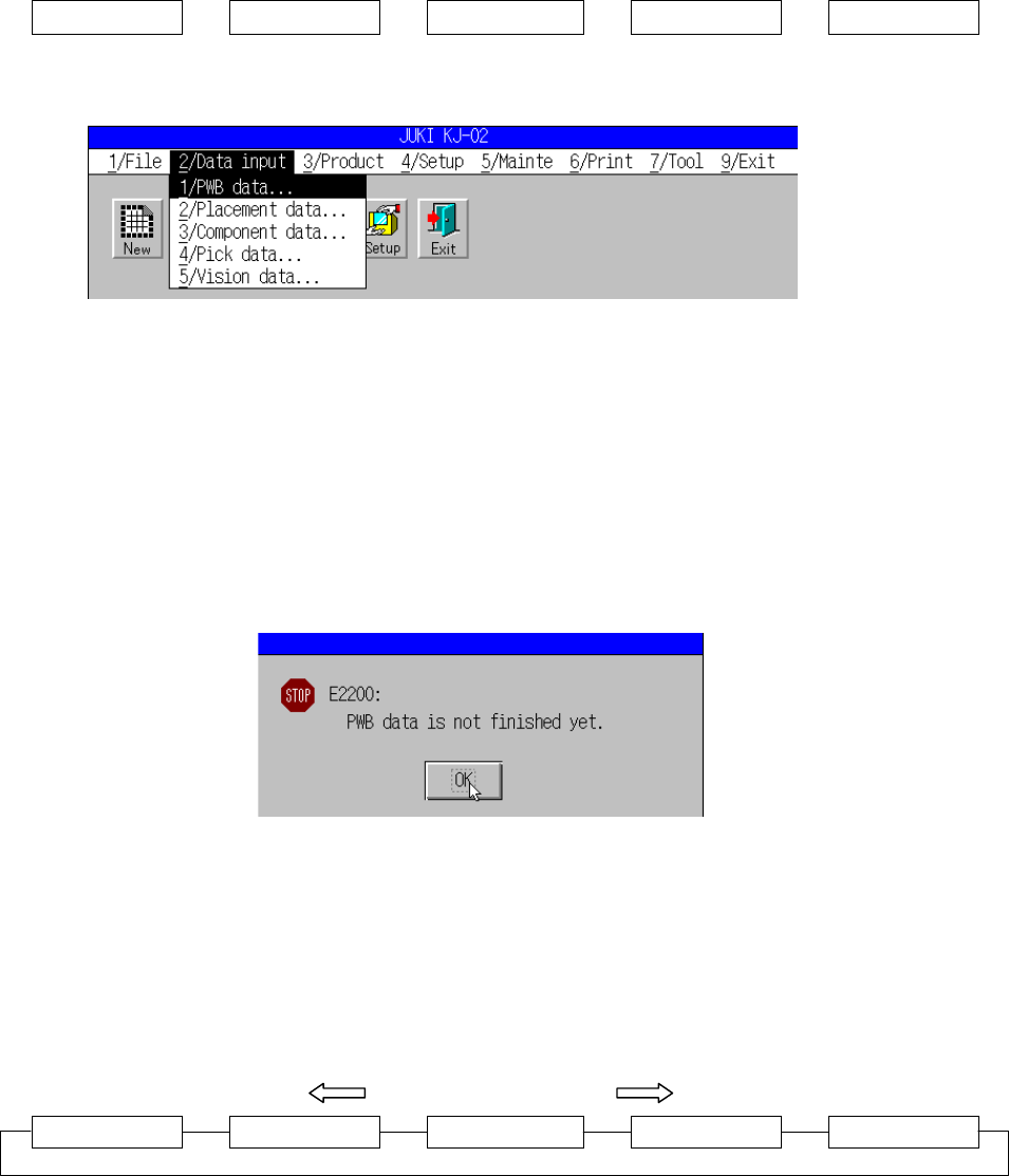
Figure 5.2.1.1 shows the screen displayed after [2/ Data Input] has been selected.
Figure 5.2.1.1 Data Input pull-down menu
A dialog box as shown in Figure 5.2.1.2 appears when you select any command
other than [1/ PWB Data] if a new program is to be created or if the board data is not
complete. When the “OK” button is pressed, the edit screen of “PWB data” appears.
In the same way, if the placement data is not complete, the component data cannot
be selected. That is, if the selected data can be created provided that the associated
data is complete, a dialog box that tells you to create the other necessary data will
appear.
Figure 5.2.1.2 Dialog box confirming incomplete PWB data
When you are through with data creation, select [3/ Chng] to move onto creating the
desired data creation.
By pressing the F6 key, the screen can be changed one after another as shown in
Figure 5.2.1.3. The order of change reverses when the key is used with the SHIFT
key.
SHIFT + F6 F6
PWB data Placement data Component data Pick data Vision data
Figure 5.2.1.3 Window selection sequence by the F6 key