KJ-01.02.Instruction Manual.REV.02.pdf - 第159页
5 − 63 <3> Working on the “T ray” w indow T he window for tray setting is shown in Figure 5.5.1. 14. Figure 5.5.1. 14 T ray setting dial og box ① Fir st pos. ( position) Enter the center posit ion (X and Y) of t he…
5 − 62
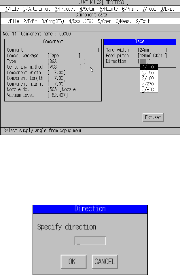
③ Direction (Component feed direction)
Define the angle of component feed according to the lot of the components.
The angle for the usually fed components shall be set to 0 degree. For the
other components with different angles, change only the feed angle.
Placement angle is not necessary to change.
Figure 5.5.1.13 Component feed direction selection screen
When selecting [5/ Other], a pop-up menu for entering placement angle appears.
Enter the desired angle within the range of 0° to 359°.
This feature can be used for the components fed at an angle of 45° such as
GaAsFET.
Direction input dialog box
5 − 63
<3> Working on the “Tray” window
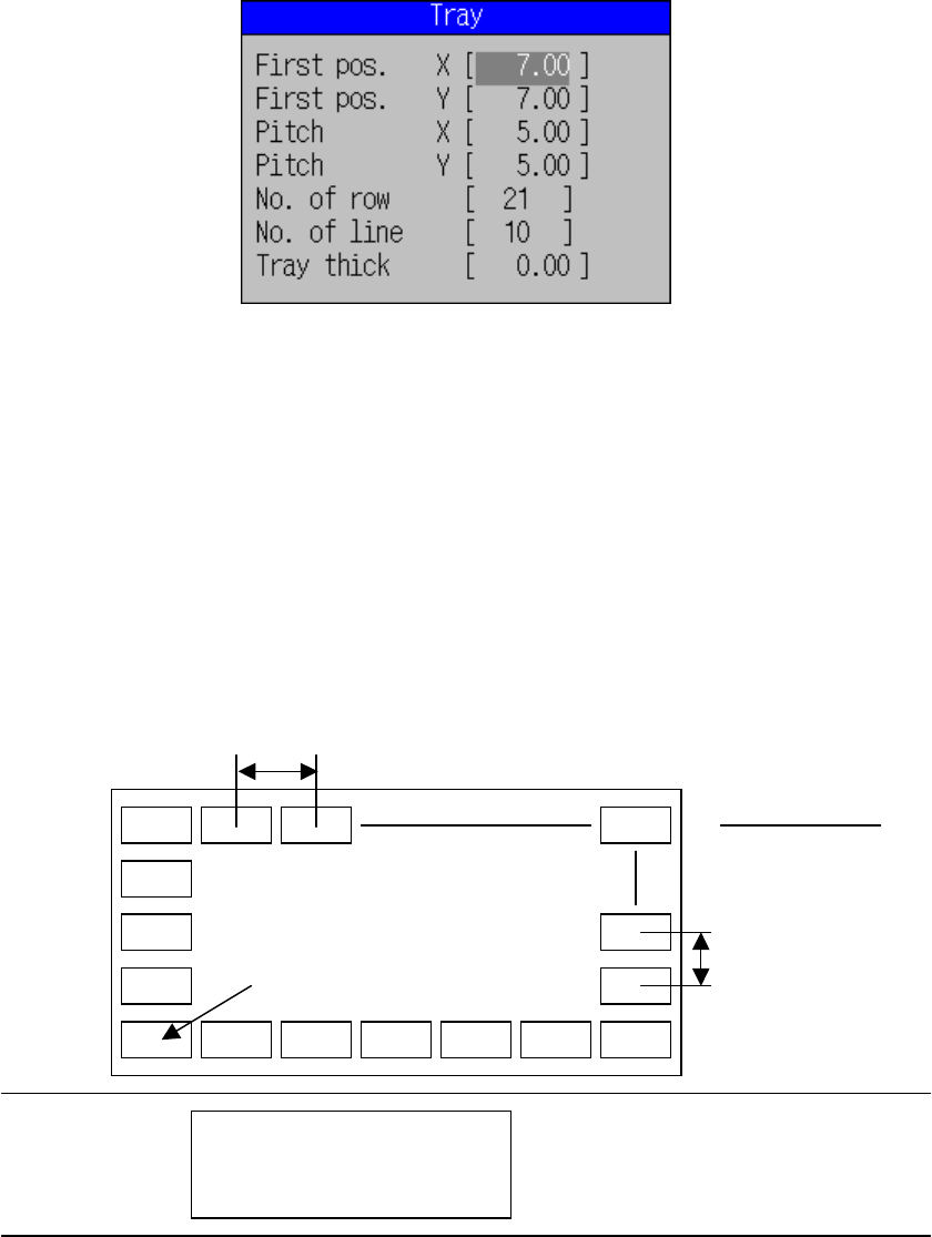
The window for tray setting is shown in Figure 5.5.1.14.
Figure 5.5.1.14 Tray setting dialog box
① First pos. (position)
Enter the center position (X and Y) of the first component on the tray,
measured from the edge of the tray.
② Pitch
Enter the pitches (pitches X and Y) between components.
③ No. of row and line (number of components)
Enter the number of components (Xn, Yn) in horizontal and vertical
directions.
Figure 5.5.1.15 Figure of First component position, pitch,
and the number of components
Yn
Xn
Tray holder
Pitch Y
First component position
Board Transport path

5 − 64
④ Tray thick
Enter the height “T” from the bottom of the tray to the surface including the
component itself.
Figure 5.5.1.16 Figure of Tray thickness
T
T
Case 1
Case 2
Component Tray