KJ-01.02.Instruction Manual.REV.02.pdf - 第38页
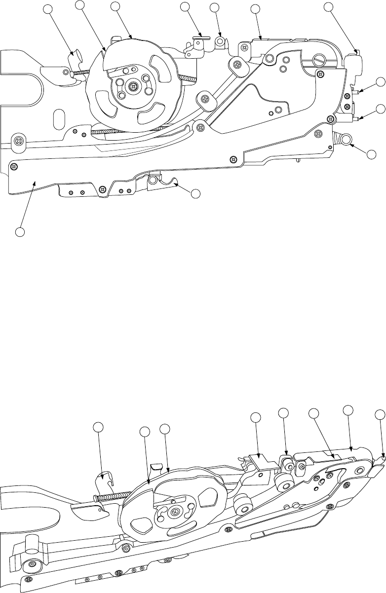
1 − 22 FF05/ 08 Parts identi ficat ion (2/2) 12 11 16 17 4 5 15 13 7 2 1 10 Figure 1.2.3.6 D etailed illustra tion of th e righ t side ① X axis ref erence pin A ⑧ Stopper ⑮ Guide co ver ② X axis ref erence pin B ⑨ Free l…
1 − 21
2. Tape feeder parts identification
The tape feeder uses a tape whose width is 8 mm, 12 mm, 16 mm, 24 mm, or 32
mm to supply components.
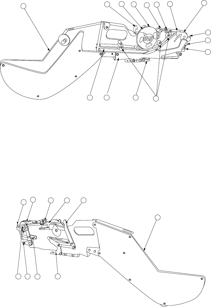
FF05/08 Parts identification (1/2)
12
11
10
16
4
17
6
5
1
2
14
19 15 13
18
Figure 1.2.3.4 Right side view
① X axis reference pin A ⑧ Stopper ⑮ Guide cover
② X axis reference pin B ⑨ Free link ⑯ Unreeling plate
③ Sprocket wheel ⑩ Tape holder ⑰ Unreeling guide roller
④ Upper cover ⑪ Cover tape fixing plate ⑱ Reel support
⑤ Upper cover hook ⑫ Lock release lever ⑲ Tape groove
⑥ Shutter ⑬ Lock holder
⑦ Knock lever ⑭ Tape guide
18
12
9
4
5
16
8
7
3 13
Figure 1.2.3.5 Left side view
1 − 22
FF05/08 Parts identification (2/2)
12
11
16
17
4
5
15
13
7
2
1
10
Figure 1.2.3.6 Detailed illustration of the right side
① X axis reference pin A ⑧ Stopper ⑮ Guide cover
② X axis reference pin B ⑨ Free link ⑯ Unreeling plate
③ Sprocket wheel ⑩ Tape holder ⑰ Unreeling guide roller
④ Upper cover ⑪ Cover tape fixing plate ⑱ Reel support
⑤ Upper cover hook ⑫ Lock release lever ⑲ Tape groove
⑥ Shutter ⑬ Lock holder
⑦ Knock lever ⑭ Tape guide
12
11
10
16
17
5
6
4
Figure 1.2.3.7 Detailed illustration of the top side
1 − 23
1.2.4 Head-related unit: parts identification
The head unit consists of the laser align sensor used to detect placement and angle
offsets of the component, and the Z slide shaft which can be moved up and down, or
be turned.
The Z slide shaft and the Z slide bracket of the Z axis are driven with rotations of the
ball screw.
The θ-axis encoder located on the upper section of the θ-axis motor detects the angle
of a component.
If a component is to be centered with the VCS, the machine switches the
component-detecting device to the detailed resolution encoder that is directly
attached on the Z-slide shaft to detect the angle of the component. This process
prevents the timing belt movement from being delayed to position a component highly
precisely.
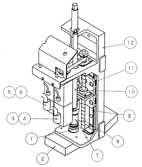
Figure 1.2.4.1 Head-related unit (General-purpose head)
① Nozzle outer ⑦ Z slide shaft
② Laser alignment sensor ⑧ Ball screw
③ Z-axis motor ⑨ Linear way
④ Z-axis encoder ⑩ Head top bracket
⑤ θ-axis motor ⑪ Head-up spring
⑥ θ-axis encoder ⑫ Z slide bracket
⑬ Detailed resolution encoder