KJ-01.02.Instruction Manual.REV.02.pdf - 第37页
1 − 21 2. T ape feeder parts ident ificat ion T he tape f eeder uses a tape whose width is 8 mm, 12 mm , 16 mm, 24 mm, or 32 mm to supply components. FF05/08 Parts identi ficat ion (1/2) 12 11 10 16 4 17 6 5 1 2 14 19 15…
1 − 20
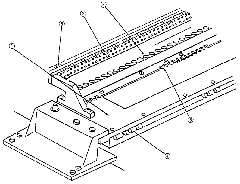
1. Feeder bank parts identification (See Figure 1.2.3.2.)
The tape feeder loaded with taped components, bulk feeder, and stick feeder
loaded with components in sticks are positioned and secured by the fixing plate
② , fixing plate B ③, and lock shaft ④ .
The tape feeder is driven by the drive cylinders ⑤ .
The position label ⑥ is used to determine the position at which each feeder is
installed.
① Feeder bank ④ Lock shaft
② Fixing plate ⑤ Drive cylinder
③ Fixing plate B ⑥ Position label
Figure 1.2.3.2
1 − 21
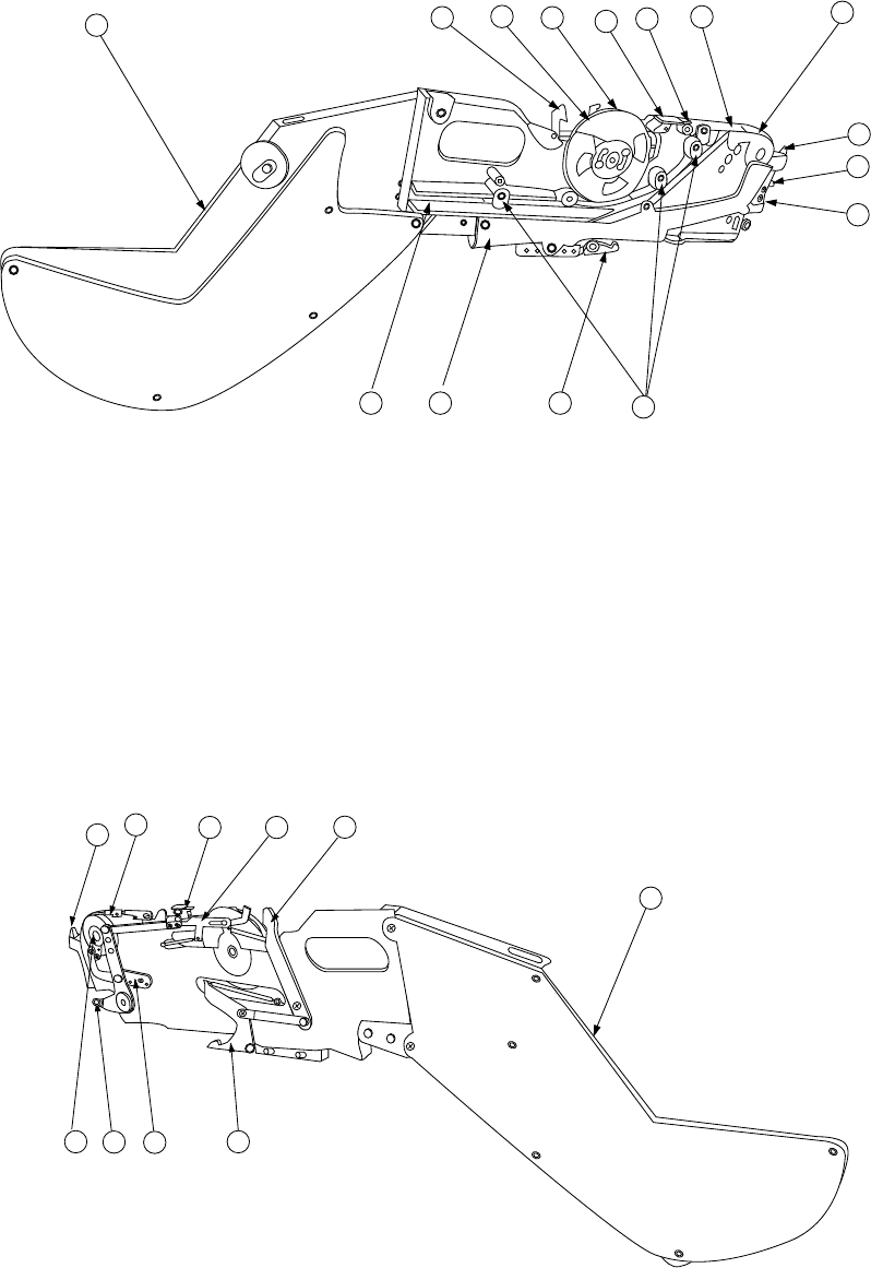
2. Tape feeder parts identification
The tape feeder uses a tape whose width is 8 mm, 12 mm, 16 mm, 24 mm, or 32
mm to supply components.
FF05/08 Parts identification (1/2)
12
11
10
16
4
17
6
5
1
2
14
19 15 13
18
Figure 1.2.3.4 Right side view
① X axis reference pin A ⑧ Stopper ⑮ Guide cover
② X axis reference pin B ⑨ Free link ⑯ Unreeling plate
③ Sprocket wheel ⑩ Tape holder ⑰ Unreeling guide roller
④ Upper cover ⑪ Cover tape fixing plate ⑱ Reel support
⑤ Upper cover hook ⑫ Lock release lever ⑲ Tape groove
⑥ Shutter ⑬ Lock holder
⑦ Knock lever ⑭ Tape guide
18
12
9
4
5
16
8
7
3 13
Figure 1.2.3.5 Left side view
1 − 22
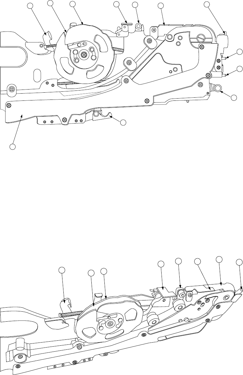
FF05/08 Parts identification (2/2)
12
11
16
17
4
5
15
13
7
2
1
10
Figure 1.2.3.6 Detailed illustration of the right side
① X axis reference pin A ⑧ Stopper ⑮ Guide cover
② X axis reference pin B ⑨ Free link ⑯ Unreeling plate
③ Sprocket wheel ⑩ Tape holder ⑰ Unreeling guide roller
④ Upper cover ⑪ Cover tape fixing plate ⑱ Reel support
⑤ Upper cover hook ⑫ Lock release lever ⑲ Tape groove
⑥ Shutter ⑬ Lock holder
⑦ Knock lever ⑭ Tape guide
12
11
10
16
17
5
6
4
Figure 1.2.3.7 Detailed illustration of the top side