KJ-01.02.Instruction Manual.REV.02.pdf - 第168页
5 − 72 (2) W hen centering a component with the VCS ( not available to a KJ-01) ① Retry time s Set this item in the same manner as when you center a component with laser . ② Placing stroke Set this item in the same manne…
5 − 71
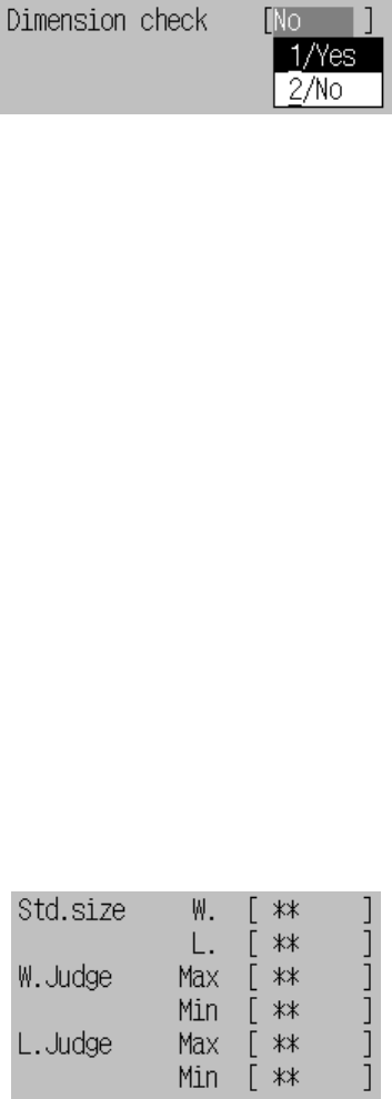
⑰ Dimension check
(* The current version of the machine (1.00) cannot use this function.)
Using the floating menu, select whether to check the dimensions of a
component. When you select “Yes”, the dimensions of a component are
automatically set as the standard dimensions, then the default value. If you
change the dimensions of a component, the default value of the standard
size is reset.
Figure of Dimension check setting
− This inspection is available only if one of the following conditions is
satisfied:
- Components are square chips, Melf, or SOTs.
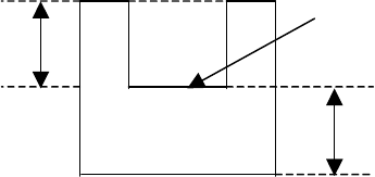
− Inspection standards
The dimensions limits (upper and lower) of a component (width and
length) are internally calculated with using the following parameters.
When the dimensions exceed the upper limit or lower limit at recognition,
the component error occurs because of a different size of component.
A) Standard size (Width and Length)
Using the formula bar, you can change the component dimensions (width
and length) which is used to decide whether the component dimensions
are appropriate. The entry range is from 0 to the actual dimensions.
B) W. Judge (Max, Min)
Using the formula bar, you can change the ratio to the standard width (Std.
Size W.) in the range from 1 % to 100 %. The smaller value you enter,
the stricter check the machine performs.
C) L. Judge (Max, Min)
Using the formula bar, you can change the ratio to the standard size in
the range from 1 to 100%. Smaller this value is, the stricter inspection is
performed.
Figure of Inspection standards setting
5 − 72
(2) When centering a component with the VCS (not available to a KJ-01)
① Retry times
Set this item in the same manner as when you center a component with laser.
② Placing stroke
Set this item in the same manner as when you center a component with laser.
③ Picking stroke
Set this item in the same manner as when you center a component with laser.
④ Trial
Set this item in the same manner as when you center a component with laser.
⑤ Picking Z down
Set this item in the same manner as when you center a component with laser.
⑥ Picking Z up
Set this item in the same manner as when you center a component with laser.
⑦ Placing Z down
Set this item in the same manner as when you center a component with laser.
⑧ Placing Z up
Set this item in the same manner as when you center a component with laser.
⑨ Theta speedSet this item in the same manner as when you center a component
with laser.
⑩ Compo. aband.
Set this item in the same manner as when you center a component with laser.
⑪ Placing offset X, Y
Set this item in the same manner as when you center a component with laser.
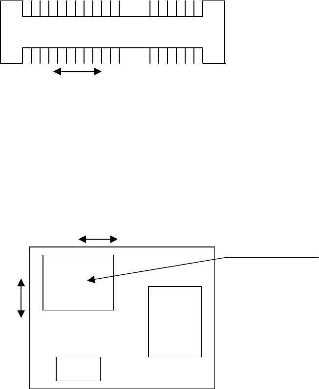
⑫ Picking depth
If the top side of a component (component height: t) is located at a higher
level than the side the machine is to pick because its shape is concave and its
sides protrude, enter the offset value (X) from the side the machine picks using
the formula bar. The allowable input value range is from 0 mm to 14 mm.
Explanation of “Picking depth”
x
t
Side to be picked up
x: pick depth
t: component height
5 − 73
⑬ Recong. offset X, Y
Enter the offset from the nozzle component pick-up point to the recognition
center point.
- Example of a connector
+ indicates the nozzle component pick-up point.
*
indicates the recognition center point.
Recognition center of a connector
In this case, X = - 7.06, and Y = 0.00.
- If the area to be picked up is limited
Recognition center offset generated if the area the machine can pick up is limited
In the case above, X =3.20 and Y = 4.00.
The range of coordinates you can enter is not affected with the component
supply angle. Enter coordinates viewed from the direction of a component
when supplied.
⑫ Dimension check
(* The current version of the machine cannot handle this function.)
See the description of the corresponding item provided when a component is
centered with laser.
+ *
7.06
*
+
+ indicates the nozzle pick-up point.
* indicates the recognition center point.
3.2
4.0
Area the machine can pick up