KJ-01.02.Instruction Manual.REV.02.pdf - 第146页
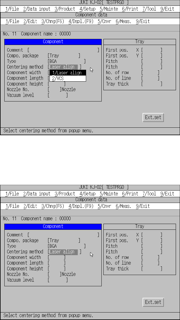
5 − 50 Figure 5.5. 1.7 Centering met hod setting screen − W hen [1/Laser align] is select ed Figure 5.5.1.8 Screen di splayed after y ou select “Laser align”
5 − 49
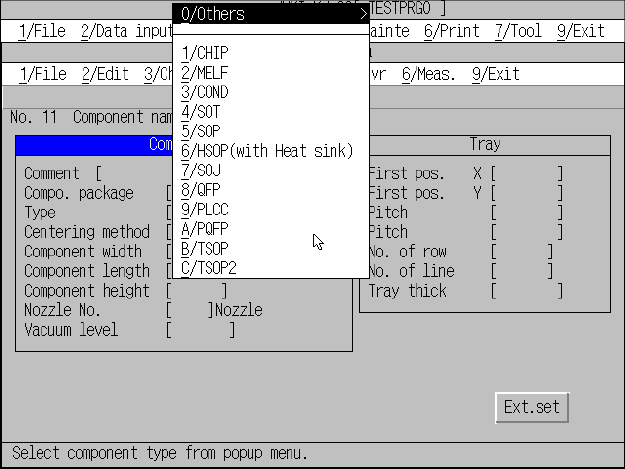
Figure 5.5.1.6 Component type setting screen
④ Centering method
When you move the cursor to this item, the centering method list box appears on
the screen as shown in Figure 5.5.1.7. Select an appropriate centering method,
“Laser align” or “VCS.”
When you do not select any of the following component types, you cannot select
“VCS” here:
SOP, QFP, PQFP, TSOP, TSOP2, BGA, FBGA, SOP (with heat sink), SOJ,
PLCC, unidirectional lead connector, bi-directional lead connector, Z-lead
connector, J-lead socket, gull-wing socket, socket with a bumper, GaAsFET,
aluminum electrolytic capacitor and outline-to-be-recognized component.
Select a
component type.
5 − 50
Figure 5.5.1.7 Centering method setting screen
− When [1/Laser align] is selected
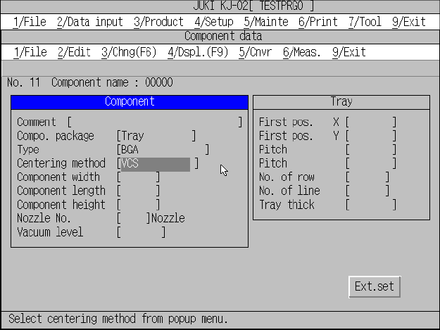
Figure 5.5.1.8 Screen displayed after you select “Laser align”
5 − 51
− When [2/VCS] is selected
Figure 5.5.1.9 Screen after [2
/
VCS] has been selected
⑤ Component dimensions
Enter the component width, length, and height using the formula bar.
Width of the component is defined in X direction with the placement angle set to
0 degree. Depth of the component is defined in Y direction with the placement
angle set to 0 degree in the same manner. For the outside dimensions, enter the
size at the laser align measurement position (see 1.1.2 “Centering system”).
The following shows the component types and shape of the components.