KJ-01.02.Instruction Manual.REV.02.pdf - 第74页
4 − 3 4.2 Operation Option W hen y ou select the [ 2/Operat ion option] com mand f rom the [ 4/Set up] m enu, the “Operat ion option” dialog box appears on the screen as shown in Figure 4.2. 1. Figure 4.2.1 Operati on op…
4 − 2
4.1 Unit System
Table 4.1.1 Unit system setting items
No. Units of measure Description
1 Length Setting of unit of length, and decimal point
2 Pressure Setting of unit of pressure, and decimal point
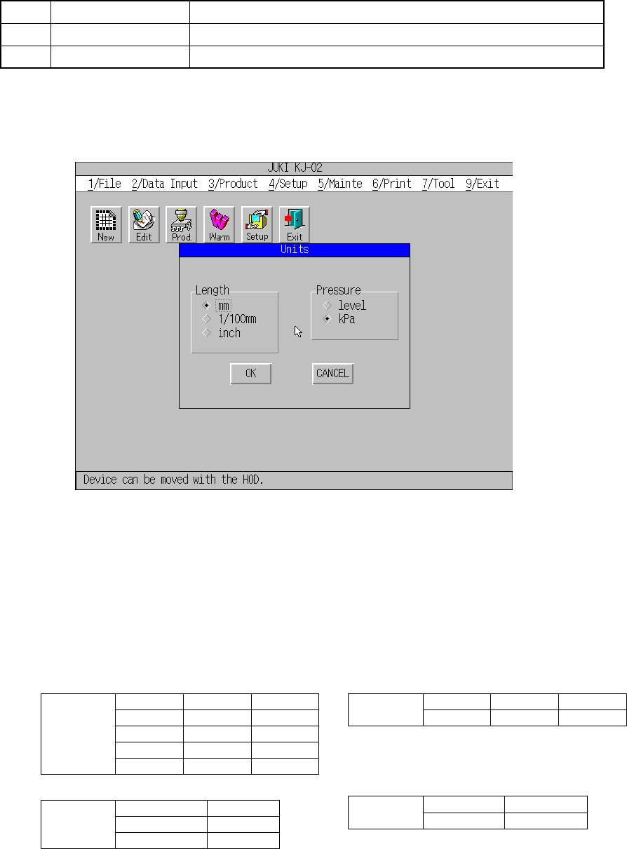
A screen as shown in Figure 4.1.1 appears when [1/ Units of measure] is
selected from [4/ Setup].
Figure 4.1.1 Units of measure screen
(1) Operation
Select the units of length and pressure with a radio button.
When the “OK” button is pressed after selections have been made, the settings
are stored in machine’s flash memory.
- Unit conversion table - Screen display (common to X, Y, Z)
mm 1/100mm inch
1 100 0.03937
0.01 1 0.0003937
25.4 2540 1
Length
0.0254 2.54 0.001
Level kPa
1 0.1333
Pressure
7.5 1
(2) Effects
All figures appear with the units set here.
Input values are also read with the units set here.
mm 1/100mm inch
Display
123.45 12345 12.123
mm 1/100mm
Display
123.12 12.123
4 − 3
4.2 Operation Option
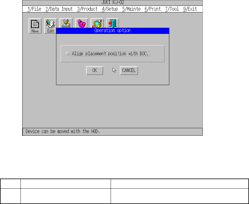
When you select the [2/Operation option] command from the [4/Set up] menu, the
“Operation option” dialog box appears on the screen as shown in Figure 4.2.1.
Figure 4.2.1 Operation option screen
(1) Setting Items
No.1 Item Description
1 Align placement position to BOC. Sets the BOC correction when the system is teaching
the placement position for editing data and so on.
(2) How to set each item
① Align placement position to BOC.
– Set whetter to align BOC or not with <Yes/No> in the check box to perform
teaching of placement point for editing, etc.
– When this option is turned ON, for placement point teaching, the placement
point is moved to the coordinate after BOC alignment. When importing the
placement point, alignment is performed reversely. So, the accurate
placement point to the PWB can be calculated for teaching.
Notes: – This alignment cannot be performed if the mark data of the PWB
data is incomplete.
– This alignment cannot be performed when not using the OCC for
machine setup.
– For the value of alignment, the latest result of mark recognition is
used. If BOC alignment is readjusted during data creation, the
result may be slightly different from the previous one.
4 − 4
4.3 Machine Setup
The following table shows the machine setup items.
Table 4.3.1 Machine setup items
No. Machine setup group Description
1 ATC nozzle setup Assign nozzles to A to R of ATC.
Set also the vacuum value for each nozzle when it is installed in the head.
Set also the laser measurement height offset for each nozzle when it is
installed inthe head.
2 Vacuum value without
nozzle
Vacuum value when the nozzle is not mounted.
3 Device enable If a device unit is defined as “not used” by this setup parameter, a production
run is completed normally even when that device unit is indispensable to the
production of the boards.
Example: If the upright chip sensor is defined as “not used” by this parameter,
no upright chip detection is made to complete the placement procedure even if
upright chip detection is commanded in the production program.
4 Reference pin position Positions of the reference and follower pins from the origin.
5 Shape clamp position Position of the edge reference from the origin.
6 Component scrap
position
The position where IC components are discarded.
The position where chip components are discarded.
7 IC conveyor belt
position
The position where the IC collection belt is installed.
The position on the IC collection belt where the components are discarded.
8 PWB conveyor Set the delay time of the PWB transport sensor (delay time of the PWB
transport sensor for a board with a cutout or hole) and that of the shape
reference Y-clamp (whether to delay the Y clamp operation or not).
9 Signal light Setting of the signal light pattern for each operation phase
10 Nozzle data
installation
Add a nozzle to be used.
11 Exit Ends the machine setup procedure.
(1) Immediately after start-up
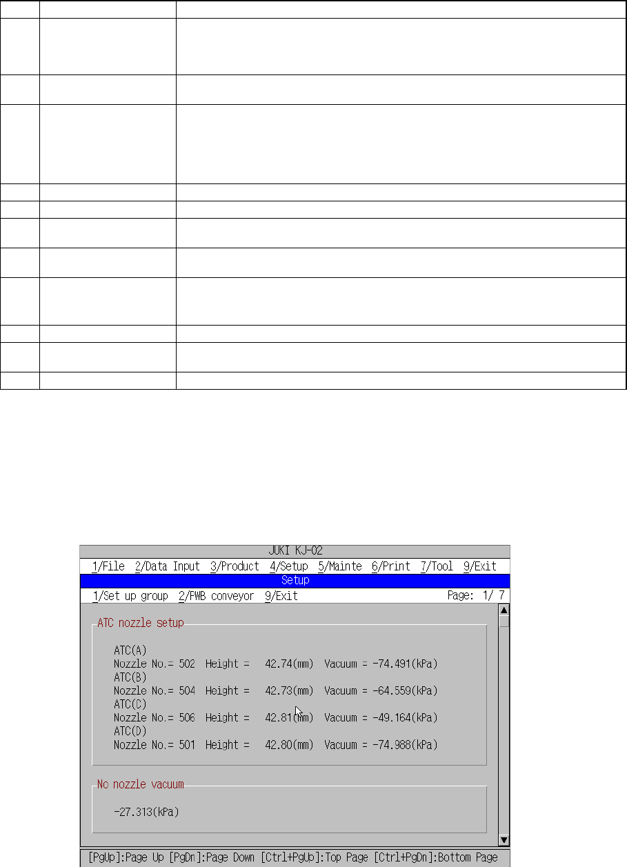
The machine setup initial screen, as shown in Figure 4.3.1 through Figure 4.3.4,
appears when [4/ Setup] and then [3/ Machine setup] is selected from the menu bar.
The machine setup initial screen shows the values defined currently for the
parameters to be set. To scroll the screen, move the scroll bar up and down using
the cursor keys or page up and down keys.
Figure 4.3.1 Machine setup initial screen (1)
Current setting for
[ATC nozzle setup], and
[Vacuum value without
nozzle],