KJ-01.02.Instruction Manual.REV.02.pdf - 第326页
10 − 1 CHA PTER 10 I/O MA NUA L CONTROL 10.1 I/O M anual C ontrol W hen y ou select the [ 4/Setup] com mand on the menu bar , and then t he [4/Manual control] command on the display ed menu, the “I/O manual control” init…
9 − 8
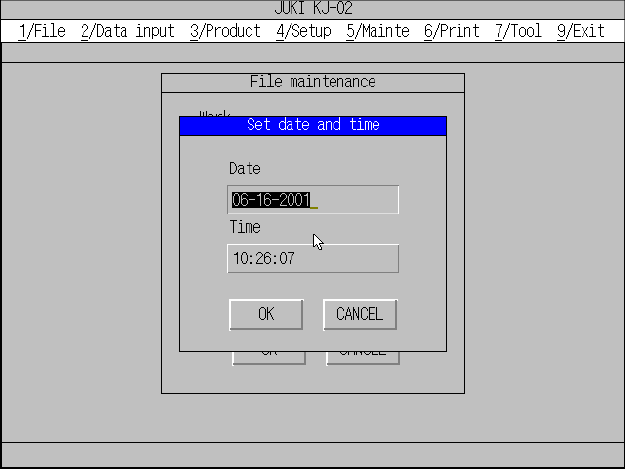
9.8 Setting the Time and Date
The command “Set date & time” is used to set the time and date.
Figure 9.8.1 Date & time setting dialog box
10 − 1
CHAPTER 10 I/O MANUAL CONTROL
10.1 I/O Manual Control
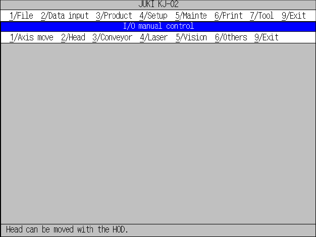
When you select the [4/Setup] command on the menu bar, and then the [4/Manual
control] command on the displayed menu, the “I/O manual control” initial screen
appears as shown in Figure 10.1.1.
Figure 10.1.1 “I/O manual control” initial screen
10 − 2
10.2 List of I/O Manual Control Setting Items
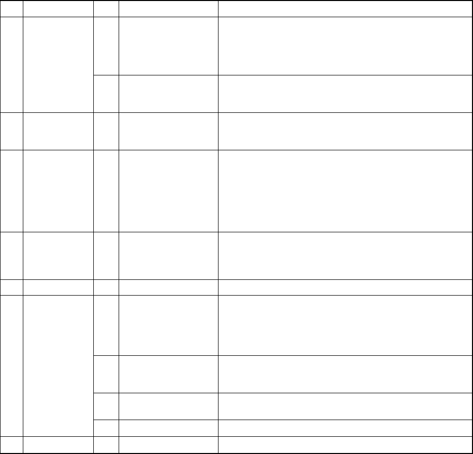
Table 10.2.1 shows the setting items on the I/O manual control screen.
Table 10.2.1 I/O Manual control
Main menu
Sub menu Description
1 XY axis
− Head XY-axis moving positions (Home position, Head
parking position, Reference pin position, Follower pin
position, Component scrap position (Chip), Component
scrap position (IC), Trash conveyor belt position, VCS
position and A given XY coordinate move)
1 Axis move
2 Z axis
− Head Z-axis moving positions (Home position, Height of
laser sensor, Height of VCS, and A given Z coordinate
move)
2 Head 1 Head control
− Nozzle control (Vacuum ON/OFF, UP/DOWN, THETA)
− Blow (ON/OFF)
− Each status display
3 Conveyor 1 Conveyor control
− Stopper pin control (ON/OFF)
− Support plate control (ON/OFF)
− Side clamp control (ON/OFF)
− Ready out control (ON/OFF)
− Board available out control (ON/OFF)
− Motor direction (ON/OFF, CW/CCW)
− Each status display
4 Laser 1 Laser control
− Laser control (Laser reset, Image display, Measure
algorithm selection, and Measure (sweep/once))
− Nozzle control (Vacuum ON/OFF, Z adjustment
(UP/DOWN), Z fine adjustment (UP/DOWN))
5 Vision 1 Live image control
− Each status display and Measurement result
1 ATC control
− Live image control
− BGA light control
− VCS light control
− BGA light control
− Each status display
2 Signal light control
− Slide plate control (OPEN/CLOSE)
− Nozzle change
− Each status display
3 Feeder knock pin
− Signal light (red, yellow, green) control (ON/OFF/BLINK)
− Signal buzzer control (ON/OFF
6 Others
9 I/O port data display
− Tape feeding action (Single/Direct knock action)
9 Exit 9 Exit
− Display of the leads that can be read