KJ-01.02.Instruction Manual.REV.02.pdf - 第363页
13 − 1 CHA PTER 13 HA NDLING THE FEEDERS A ND OPTIONS 13.1 Replacement of the Tape Feeder 13.1.1 Replacement of the t ape feeder (8 mm, 12 mm, 16 mm, 24 mm, and 32 mm) CA UTION Do not replace the tape f eeder with anothe…
12 − 5
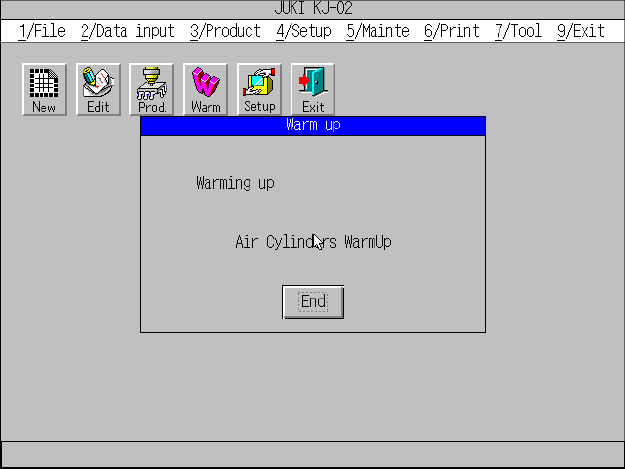
The following screen is being displayed during warm-up.
When you click the <END> button or press the ENTER key, the machine finishes
warming up.
13 − 1
CHAPTER 13 HANDLING THE FEEDERS AND
OPTIONS
13.1 Replacement of the Tape Feeder
13.1.1 Replacement of the tape feeder
(8 mm, 12 mm, 16 mm, 24 mm, and 32 mm)
CAUTION
Do not replace the tape feeder with another one while the X- or Y-axis, or head
is operating. It may cause a serious injury to the operator or damage the
machine itself since the tape feeder touches the operating parts.
Do not dismount the tape feeder while the X- or Y-axis or head is operating.
After you mount the feeders required for producing boards at the position
specified with a production program, mount feeders, which are not used for
production, such as 8-mm tape feeders where no feeders are mounted to
prevent any gap from being generated between the already mounted feeders.
This operation secures your safety since it prevents your finger or hand from
accidentally being slid into such a gap.
Mounting
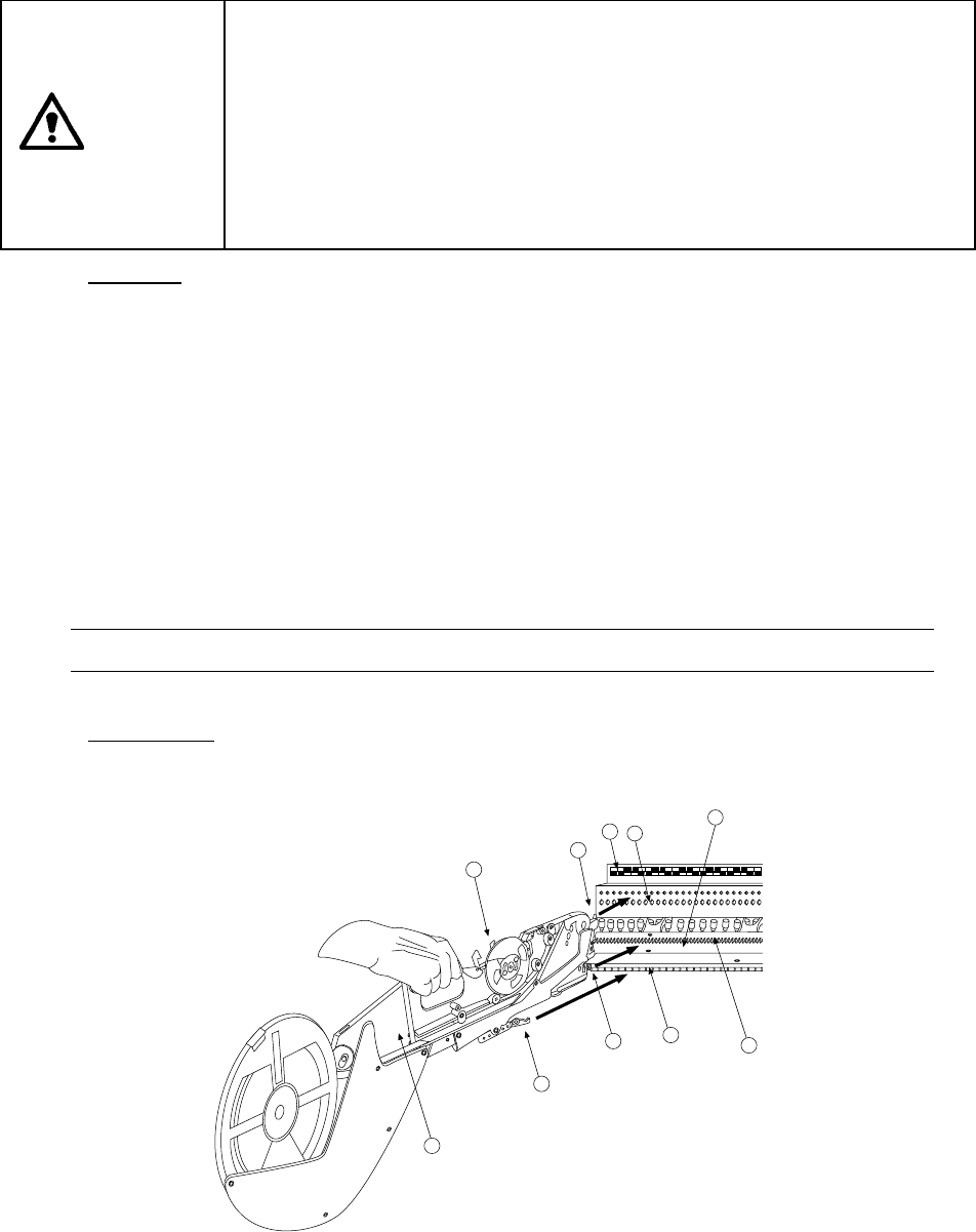
1) Place the bottom of the tape feeder ① on the feeder bank ②
2) Slide the tape feeder ① toward the positioning hole of the fixing plate ③, and
align the guide pin located on the bottom of the tape feeder with the fixing plate
B7 as a guide. Fit the positioning pin on the front of the tape feeder into the
positioning hole of the fixing plate ③. To do so, while pulling the lock release
lever ⑩ gently, align the lock holder ⑨ with the V-shaped groove of the lock
shaft ⑧, then push the front of the tape feeder against the fixing plate.
Release the lock release lever to clamp the lock shaft with the lock holder and
fix the tape feeder.
In this case, the number of the position label ④ pasted just above the hole into
which the positioning pin on the front of the tape feeder is fit indicates the
position at which the tape feeder is mounted.
Note: Check to see if the tape feeder is off the feeder bank or not upright.
Dismounting
1) Hold the tape feeder ① and pull it back to you while pulling the lock release
lever ⑩.
10
5
8
2
9
6
3
4
7
1
Figure 13.1.1.1
13 − 2
13.1.2 Replacement of 32-mm adhesive tape feeder
CAUTION
Do not replace the tape feeder with another one while the X- or Y-axis, or head
is operating. It may cause a serious injury to the operator or damage the
machine itself since the tape feeder touches the operating parts.
Do not dismount the tape feeder while the X- or Y-axis or head is operating.
After you mount the feeders required for producing boards at the position
specified with a production program, mount feeders, which are not used for
production, such as 8-mm tape feeders where no feeders are mounted to
prevent any gap from being generated between the already mounted feeders.
This operation secures your safety since it prevents your finger or hand from
accidentally being slid into such a gap.
Mounting
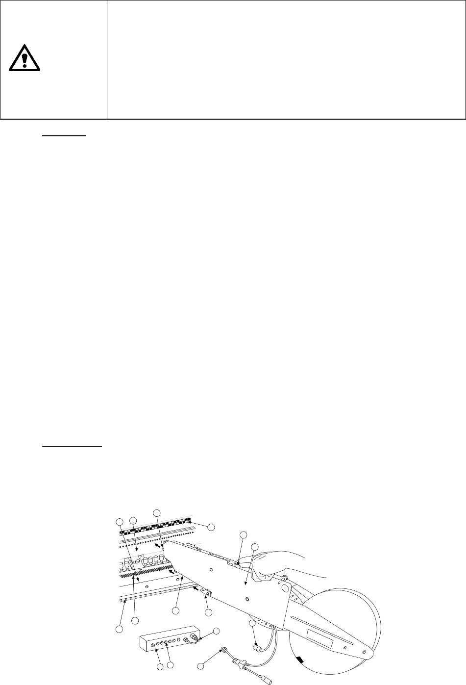
1) Place the bottom of the tape feeder ① on the feeder bank ②.
2) Slide the tape feeder ① toward the positioning hole of the fixing plate ③, and
align the guide pin located on the bottom of the tape feeder with the fixing plate
B7 as a guide. Fit the positioning pin on the front of the tape feeder into the
positioning hole of the fixing plate ③. To do so, while pulling the lock release
lever ⑩ gently, align the lock holder ⑨ with the V-shaped groove of the lock
shaft ⑧, then push the front of the tape feeder against the fixing plate.
Release the lock release lever to clamp the lock shaft with the lock holder and
fix the tape feeder.
In this case, the number of the position label ④ pasted just above the hole into
which the positioning pin on the front of the tape feeder is fit indicates the
position at which the tape feeder is mounted.
3) Match the index of the power cord connector ⑪ with the power supply part ⑬
of the connector bracket ⑫ (place the white dot to the right), and insert the
connector until you hear a click sound of the click stop.
4) Insert the air coupler ⑮ into the female union ⑭ until you hear a click sound
of the click stop.
5) Set the feeder float sensor that is located on the side a 32-mm adhesive tape
feeder (NF3SN) is installed so that it cannot be used: you uncheck the check
box “Front feeder float detection” or “Rear feeder float detection” on the “Std
Device enable” menu invoked from the Machine Setup menu.
Dismounting
1) Push forward the slide part of the female union ⑭, to detach the air coupler ⑮.
2) Pull the slide part of the power cord connector ⑪ toward your side, and
disconnect the connector.
3) With pulling the lock release lever ⑩, pull back the tape feeder ① to remove it
5
11
14
13
15
12
6
7
8
9
2
1
3
10
4
Figure 13.1.2.1