KJ-01.02.Instruction Manual.REV.02.pdf - 第105页
5 − 9 5.2.2 Reading the program If you wi sh to read anot her prog ram af ter you have entered the pr oduction prog ram edit mode, select [1/ O pen] of [1/ File] fr om the local menu. W hen the machine has completed read…
5 − 8
5.2 Data Input
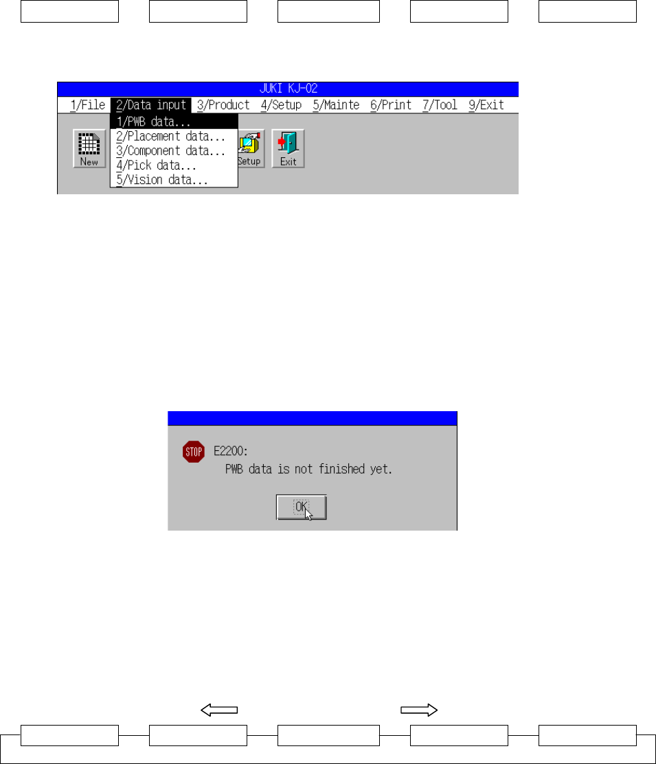
To enter the program edit mode, select [2/ Data Input] from the menu bar.
5.2.1 Creating the program
The production program is created in the following order:
PWB data
→
→→
→
Placement data
→
→→
→
Component data
→
→→
→
Pick data
→
→→
→
Vision data
Figure 5.2.1.1 shows the screen displayed after [2/ Data Input] has been selected.
Figure 5.2.1.1 Data Input pull-down menu
A dialog box as shown in Figure 5.2.1.2 appears when you select any command
other than [1/ PWB Data] if a new program is to be created or if the board data is not
complete. When the “OK” button is pressed, the edit screen of “PWB data” appears.
In the same way, if the placement data is not complete, the component data cannot
be selected. That is, if the selected data can be created provided that the associated
data is complete, a dialog box that tells you to create the other necessary data will
appear.
Figure 5.2.1.2 Dialog box confirming incomplete PWB data
When you are through with data creation, select [3/ Chng] to move onto creating the
desired data creation.
By pressing the F6 key, the screen can be changed one after another as shown in
Figure 5.2.1.3. The order of change reverses when the key is used with the SHIFT
key.
SHIFT + F6 F6
PWB data Placement data Component data Pick data Vision data
Figure 5.2.1.3 Window selection sequence by the F6 key
5 − 9
5.2.2 Reading the program
If you wish to read another program after you have entered the production program
edit mode, select [1/ Open] of [1/ File] from the local menu. When the machine has
completed reading the program, the PWB data screen appears.
5.3 PWB Data
5.3.1 Default setting
Different PWB-data initial screens appear depending on whether the basic setting
data has been created or not (the data being incomplete).
(1) When the basic setting has not been completed:
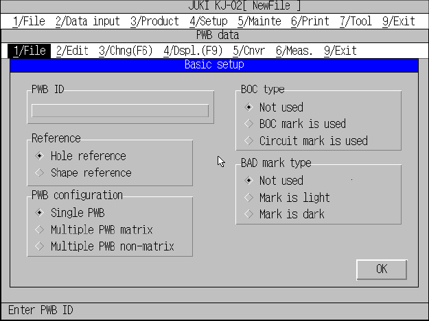
A screen appears as shown in Figure 5.3.1.1 when [1/ PWB data] is selected.
Figure 5.3.1.1 PWB data initial screen (Basic setting yet to be completed)
Use the edit box to set the PWB ID, and use the radio button to set reference
method, PWB configuration, BOC type, and Bad mark type.
To change to another item, use the TAB key or the SHIFT and TAB key.
When the “OK” button is selected, the input focus moves onto the “Dimension
setting” window, just as when the basic setting data has been created. The
“Dimension setup” window varies depending on the settings made in basic
setting.
Note: Before you load a board, click the <OK> button to confirm the setting of
“Reference”. (“Hole reference” is set by default on new PWB data.)
5 − 10
(2) When the basic setting has been completed:
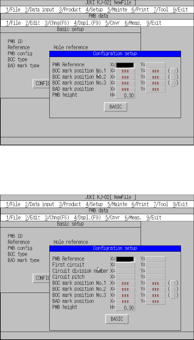
If [1/ PWB data] is selected when the basic setting has been completed, different
screens will appear depending on the settings made for PWB configuration of
the basic setting. Figures 5.3.1.2, 5.3.1.3, and 5.3.1.4 show possible screens
that will appear at this time. The input focus is in the “Configration setup” window.
Single pattern
Figure 5.3.1.2 PWB data initial screen (Single pattern)
Matrix multiple patterns
Figure 5.3.1.3 PWB data initial screen (Matrix multiple patterns)