KJ-01.02.Instruction Manual.REV.02.pdf - 第187页
5 − 91 (3) Chn g See t he description of “Chng ” on the PW B data screen f or how to operate this command. (4) Dsp l. T his command switches the scr eens between the Pick data displayed in input order and that in feeder …
5 − 90
3) Duplicate]
The line on which the cursor is located is inserted (copied) to the next line.
The parameters that are copied are the “Component name” and “Package”,
with the remainders initialized.
4) Find
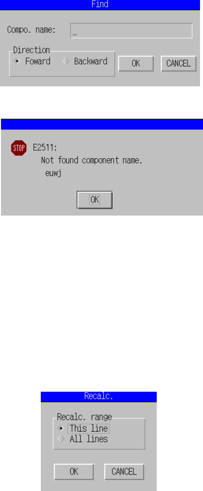
This command searches a component name through Pick data. When you
select the [7/Find] command, the “Find” dialog box appears on the screen as
shown in Figure 5.6.6.5. If the machine does not find a name you entered,
the error dialog box appears on the screen.
Figure 5.6.6.5 Pick data finding dialog box
Figure 5.6.6.6 Find error dialog box
5) Pick point recalc
This command displays the following dialog box to ask you whether the
pick-up coordinates of the line the cursor is located should be calculated
again or those of all lines should be calculated again.
The machine recalculates the pick-up coordinates of the current line or all
lines according to your selection.
If you have not entered the component pick-up coordinates (X1, Y1) on a
tray holder, the machine will not recalculate the pick-up coordinates of the
line(s) since the machine calculates that of the line(s) based on the
component pick-up position (X1, Y1).
Figure 5.6.6.7 Pick-up point recalculation dialog box
6) Mark database
This command deletes/modifies data registered onto the mark database.
See Section 6.4 “Mark Database Management” for details
5 − 91
(3) Chng
See the description of “Chng” on the PWB data screen for how to operate this
command.
(4) Dspl.
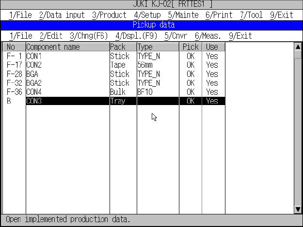
This command switches the screens between the Pick data displayed in input
order and that in feeder order.
On the screen displaying Pick data in feeder order, you can see the data only,
and cannot edit any data.
Figure 5.6.6.8 shows the screen displaying Pick data in feeder order.
Figure 5.6.6.8 Displaying Pick data in feeder order
The cursor moves up or down with pressing the ↑ or ↑ key. When you press the
↑ key on the top line or ↑ key on the bottom line, the screen is scrolled.
The PageUp or PageDown key scrolls the screen by one page.
When you press the Enter key, the machine switches the current screen to the
screen that allows you to enter data on the line the cursor is located.
(5) Cnvr (Conveyor) menu
The operation is the same as that for [5/ Cnvr] of PWB data.
(6) Meas. (Measurement) menu
Not available with the placement data.
(7) Exit menu
The same as the end of [Exit].

5 − 92
5.7 Measurement
Only when you display Component data while you are editing a production program,
you can select the [6/Meas.] command and then the [1/Single Measurement]
command.
5.7.1 Measurement
5.7.1.1 Measurement type
The measurement items are divided as follows:
Measurement item Measured data Data subject to measurement Remarks
Vac. level of comp. pick Component data Vacuum pressure for component pick
up
Height Component data Component height
Laser height
Chip rise acceptable value
The machine measures the
laser height and the value used
for judging whether a tombstone
error occurs only for a
component centered with laser.
Outline Component data Dimensions of a component, horizontal
width
Dimensions of a component, vertical
length
Lead info Vision data Lead pitch Length of a lead
Number of leads
Missing leads (first missing lead
and number of missing leads)
5.7.1.2 Function
5.7.1.2.1 Measurement function
(1) Function
– Vac. level of comp. pick
The vacuum pressure for component pick is measured.
Note: When the measurement item “Outline” is selected, and the nozzle
number is changed at the component dimensions measurement
operation, the initial value is set for a new nozzle.
– Height
The height of a component is measured by moving the component upward
and downward, then obtaining the existence of its shade with the laser.
• The laser height is calculated according to the component height and
component type measured (only for the laser centering components).
• The acceptable values when the chip rise is detected are calculated
according to the component height and component type measured (only
for the laser centering components).
– Outline
For laser centering components
• Laser recognition is performed on components, and angle of the
components is recognized. When recognition is complete, with rotating
the component by 0 degrees and by 90 degrees, the laser width data in
each angle is obtained as the data for length and width of the
component.
Note: Some components cannot be measured. See “Component type”
of “(2) Limited items” for details.