KJ-01.02.Instruction Manual.REV.02.pdf - 第39页
1 − 23 1.2.4 Head-related unit: parts identification The head unit consist s of t he laser align sensor used to detect placement and ang le offset s of t he component, and the Z slide shaf t which can be moved up and dow…
1 − 22
FF05/08 Parts identification (2/2)
12
11
16
17
4
5
15
13
7
2
1
10
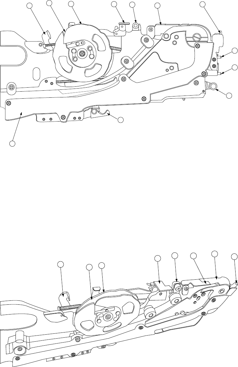
Figure 1.2.3.6 Detailed illustration of the right side
① X axis reference pin A ⑧ Stopper ⑮ Guide cover
② X axis reference pin B ⑨ Free link ⑯ Unreeling plate
③ Sprocket wheel ⑩ Tape holder ⑰ Unreeling guide roller
④ Upper cover ⑪ Cover tape fixing plate ⑱ Reel support
⑤ Upper cover hook ⑫ Lock release lever ⑲ Tape groove
⑥ Shutter ⑬ Lock holder
⑦ Knock lever ⑭ Tape guide
12
11
10
16
17
5
6
4
Figure 1.2.3.7 Detailed illustration of the top side
1 − 23
1.2.4 Head-related unit: parts identification
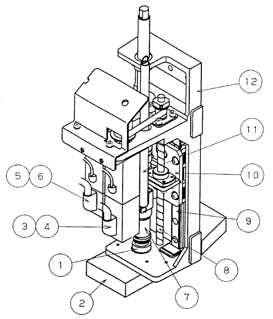
The head unit consists of the laser align sensor used to detect placement and angle
offsets of the component, and the Z slide shaft which can be moved up and down, or
be turned.
The Z slide shaft and the Z slide bracket of the Z axis are driven with rotations of the
ball screw.
The θ-axis encoder located on the upper section of the θ-axis motor detects the angle
of a component.
If a component is to be centered with the VCS, the machine switches the
component-detecting device to the detailed resolution encoder that is directly
attached on the Z-slide shaft to detect the angle of the component. This process
prevents the timing belt movement from being delayed to position a component highly
precisely.
Figure 1.2.4.1 Head-related unit (General-purpose head)
① Nozzle outer ⑦ Z slide shaft
② Laser alignment sensor ⑧ Ball screw
③ Z-axis motor ⑨ Linear way
④ Z-axis encoder ⑩ Head top bracket
⑤ θ-axis motor ⑪ Head-up spring
⑥ θ-axis encoder ⑫ Z slide bracket
⑬ Detailed resolution encoder
1 − 24
1.2.5 ATC unit (Automatic tool changer): parts identification
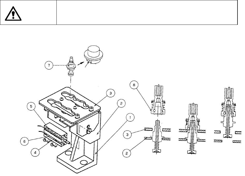
The slide plate ③ hooks the nozzle outer ⑧ and removes the nozzle ⑦ with air
supplied from the head unit, and attaches it with air sucked by the head unit. The air
cylinder ④ opens or closes the slide plate ③ to remove out/store the nozzle.
When you have to replace the current nozzle with another one due to changeover of
the feeder, manually push and open the slide plate ③.
WARNING
To prevent injury to the body which can be caused by an accidental
activation of the machine, cut off the power to the machine before
starting nozzle change.
Figure 1.2.5
① ATC mounting base ⑤ ATC OPEN sensor
② ATC base ⑥ ATC CLOSE sensor
③ Slide plate ⑦ Nozzle
④ Air cylinder ⑧ Nozzle outer
Cut side