KJ-01.02.Instruction Manual.REV.02.pdf - 第23页
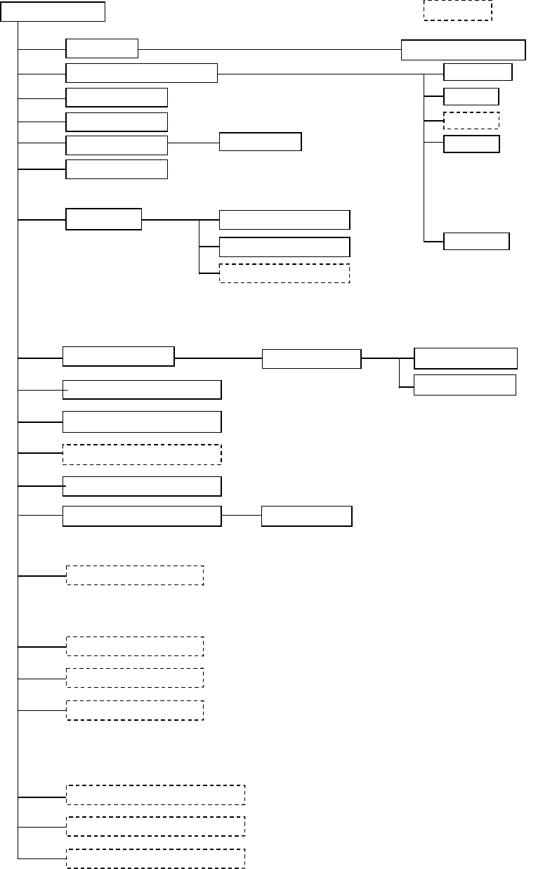
1 − 7 1.1.3.2 Signal t ower Em ergency stop but ton Placi ng head Placem ent s tati on T ape feeder Stic k feeder IC col lecti on belt Bulk f eeder KJ-02 Optio nal Pin referenc e Shape clam p Laser recognit ion head Bad …
1 − 6
1.1.3 System configuration
1.1.3.1
CRT display
Keyboard
Track ball
FDD
Area sensor
Signal tower
Emergency stop button
Placing head
Automatic tool changer (ATC)
Feeder float detecting function
Pneumatic piping system
Vision Centering System (VCS)
Feeder bank driver
Vision monitor
PWB conveyor unit
Placement station
Tape feeder
Stick feeder
Matrix tray holder
Power unit
CPU board (Flash memory)
I/O control CPU
Motor control unit
Cabinet
X-Y positioning unit
Bulk feeder
KJ-01
Optional
Calibration block (Maintenance tool)
External Programming Unit (EPU)
Pin reference
Shape clamp
Laser recognition head
Bad mark reader
Offset correction camera
M sizes board correspond
1 − 7
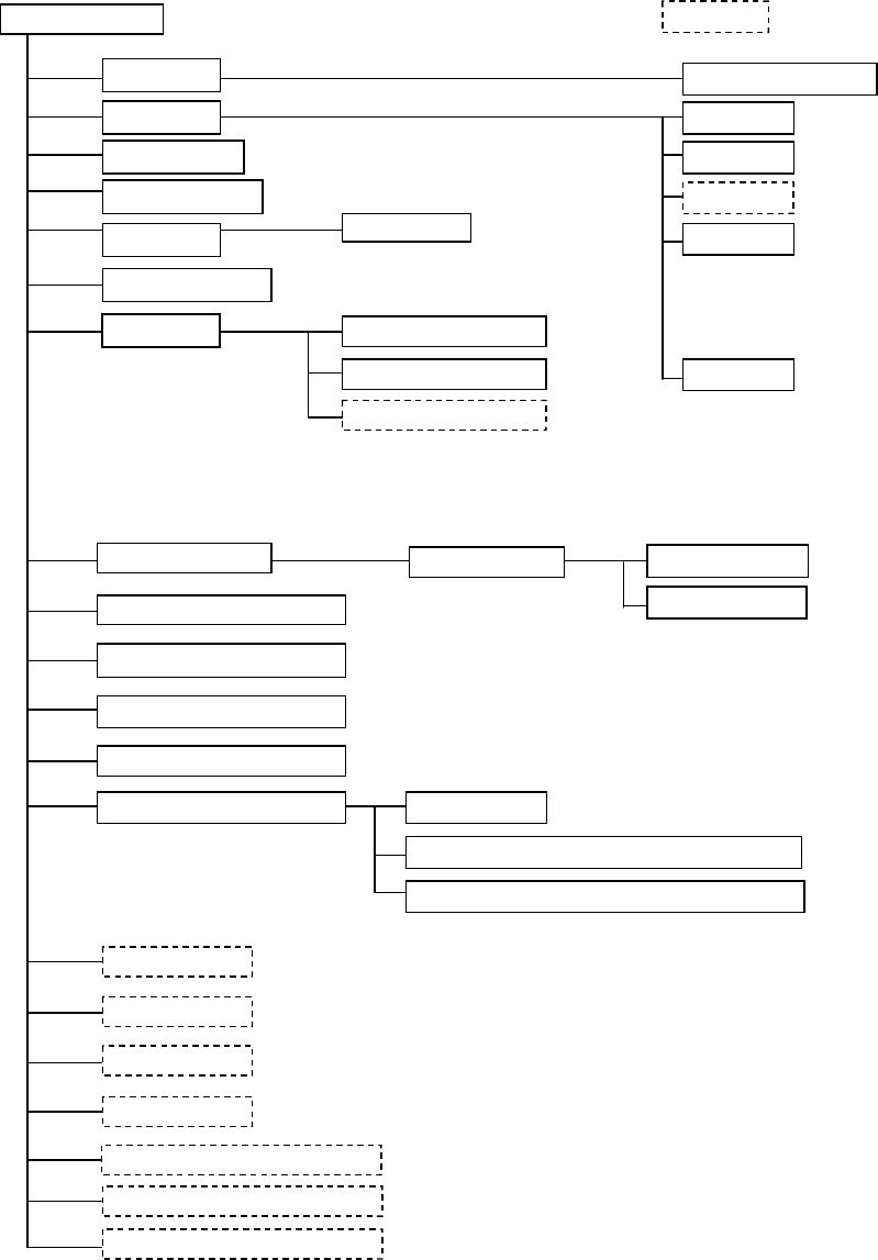
1.1.3.2
Signal tower
Emergency stop button
Placing head
Placement station
Tape feeder
Stick feeder
IC collection belt
Bulk feeder
KJ-02
Optional
Pin reference
Shape clamp
Laser recognition head
Bad mark reader
Offset correction camera
Power unit
CPU board
I/O control CPU
Motor control unit
Cabinet
X-Y positioning unit
CRT display
Keyboard
Track ball
FDD
Area sensor
Automatic tool changer (ATC)
Feeder float detecting function
Pneumatic piping system
Vision Centering System (VCS)
Feeder bank driver
PWB conveyor unit
Matrix tray holder
Calibration block (Maintenance tool)
External Programming Unit (EPU)
Vision monitor
Component-recognizing camera(24 x 24mm)
Large component-recognizing camera (50 x 50mm)
*
1
*
1
*1:Choose one of these Cameras

1 − 8
1.1.4 Mechanical specifications
• Placement accuracy
The following table lists the placement accuracy data for different types of
components. A poorer accuracy results depending on the components that may
have an edge or plastic mold burrs at the area detected with the laser align
function, and that may have a moving part to be detected with respect to the pick
port.
Table 1.1.4.1
KJ-01/02
LAHD heads (Laser recognition correction)
Component size: 20 mm x 20 mm or less, or 23.5 mm x 11 mm or less
Component type
Position (X, Y) Unit: (mm)
Posture (theta) Unit: (°)
Square chip
± 0.08 ± 3
MELF
± 0.1
± 3
SOT
± 0.15
± 3
Aluminum
electrolytic capacitor
± 0.3 ± 10
SOP ± 0.15 in the right angle direction
against the lead
(Burr on one side: 0.15 or less)
±0.2 in the direction parallel to the
lead
± 3
PLCC
± 0.2
± 0.3
QFP, TSOP
(Pitch: 0.8 or more)
± 0.12
± 0.3
QFP, TSOP
(Pitch: 0.65)
± 0.08
± 0.3
BGA ± 0.2
± 0.3
Other large-size
components
± 0.3
−
• Placement cycle time
The optimized placement cycle time is shown below. The cycle time required
when a component is placed on a board actually varies depending on the board
size or how many times a nozzle is replaced.
Small chip component
4,000 components/hour 0.9 seconds/component)
This cycle time is calculated with supposition that the machine picks up a
component from an 8-mm tape feeder and places it on a board at 180 degrees,
and the distance from the component pick-up point to the placement point is 80
mm or less.
[Definition]