KJ-01.02.Instruction Manual.REV.02.pdf - 第267页
7 − 17 7.4 Mark Database M anagement This command delet es or edits dat a regist ered in the mar k database. 1) Select [D/M ark database...] on the Edit menu. Fig. 7.4. 1.1 “Edit” Menu Mark 2) Display s the mar k databas…
7 − 16
3) Pattern which cannot be registered as the user defined template
① IC marks
② Silk (character) pattern
Since the pattern and pad generation process is totally different from the silk
printing process, the placement position cannot be determined based on the
silk print.
③ Pad and land pattern printed on the silk screen
The solder paste on the screen is in the form of grains, so lighting cannot be
stable depending on the environment or condition. The template matching
is highly appropriate for change of lighting conditions, but not for the change
of polarity (positive and negative).
④ The similar pattern is located on the same recognition screen
⑤ Template whose contrast difference is insufficient
7 − 17
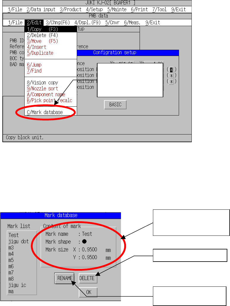
7.4 Mark Database Management
This command deletes or edits data registered in the mark database.
1) Select [D/Mark database...] on the Edit menu.
Fig. 7.4.1.1 “Edit” Menu Mark
2) Displays the mark database management
This dialog box allows you to edit the mark database.
Fig. 7.4.2.1 Mark Database Management Dialog Organization
“Mark database
management” has been
added to the program
editing menu.
Changes the mark data
name.
The display of the contents
of mark registration has
been added.
Deletes mark data.

8 − 1
CHAPTER 8 PRODUCTION PROCEDURES
8.1 Preparations
8.1.1 Component feeders
Make sure that all component feeders (the tape feeders, the stick feeders, and the
matrix tray holder) are mounted in place correctly. Particularly.
8.1.2 ATC
Make sure that the nozzle numbers mounted on the ATC are equal to those of the
ATC numbers and nozzle numbers selected in “ATC nozzle assignment” of the
machine setup.
<Mounting and demounting nozzles on the ATC>
Procedure
1. Turn off the power of the machine.
2. Open the slide plate ③. When you push the ATC angle ④ toward the air
cylinder ⑤, the slide plate opens.
3. Face the cut-in side of the nozzle ⑨ as shown in the figure, and fit the nozzle in
the hole of the ATC base ② to attach it on the ATC.
4. Nozzles are also dismounted in this state.
5. Do not attach the nozzle directly to the head. (The face of the laser becomes
dirty and this can cause errors.)
Notes: If you return a nozzle to the original position (before removing the nozzle),
and replace it with another nozzle, set the “Height” by clicking the <EXEC>
button on the “ATC nozzle setup” screen invoked from the “Setup” menu.
WARNING
Before starting to work, turn off the power of the machine to avoid a
risk of injury caused by unpredictable activation of the machine.