KJ-01.02.Instruction Manual.REV.02.pdf - 第89页
4 − 18 4.3.7 IC collection belt position W hen y ou select the [ 7/ IC collection belt position] com mand f rom the [ 1/Set up group] menu, the “ IC collection belt position” dialog box appears on the screen as shown in …
4 − 17
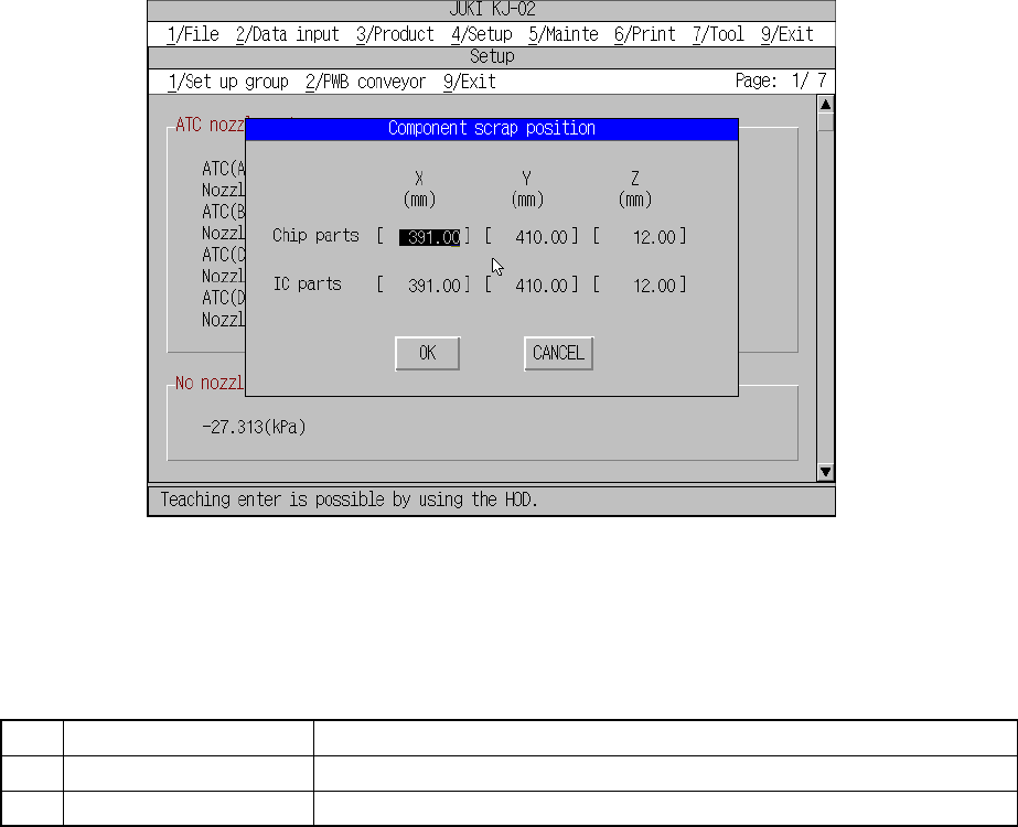
4.3.6 Component scrap position
When you select the [6/ Component scrap position] command from the [1/Set up
group] menu, the “Shape clamp position” dialog box appears on the screen as shown
in Figure 4.3.6.1.
Figure 4.3.6.1 Component scrap position setting dialog box
(1) Setting items
No. Item Description
1 Chip parts The scrap position for chip components
2 IC parts The scrap position for IC components
(2) Setting the position
– Key in X and Y coordinate value directly from the keyboard.
– Use the HOD to teach and enter the coordinates. In this case, either X or Y
can be in focus.
– Z must be in focus when it is taught.
4 − 18
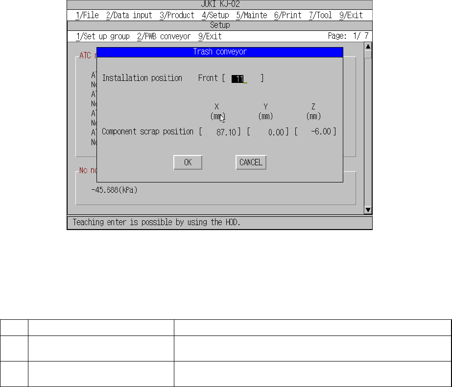
4.3.7 IC collection belt position
When you select the [7/ IC collection belt position] command from the [1/Set up
group] menu, the “IC collection belt position” dialog box appears on the screen as
shown in Figure 4.3.7.1.
Figure 4.3.7.1 IC collection belt position setting dialog box
(1) Setting items
No. Item Description
1 Installation position
(Feeder hole number)
Installed position of IC collection belt
2 Component scrap position
(X, Y, Z)
Component scrap position on the IC collection belt
(2) Setting the position
① How to set installation position
– Set the installation position of IC collection belt.
– Enter the feeder hole number in the edit box.
Note: When you enter a value in the Edit box, and press the <Return> key,
the machine automatically calculates the component scrap position.
Check this position with the teaching function.
② Component scrap position
– Key in X, Y, and Z coordinate value directly from the keyboard.
– Using the HOD, enter the value by teaching. In this case, the value is
obtained at the same time with the input focus set in either X or Y.
– To perform teaching of a Z coordinate, the input focus must be set in Z.
4 − 19
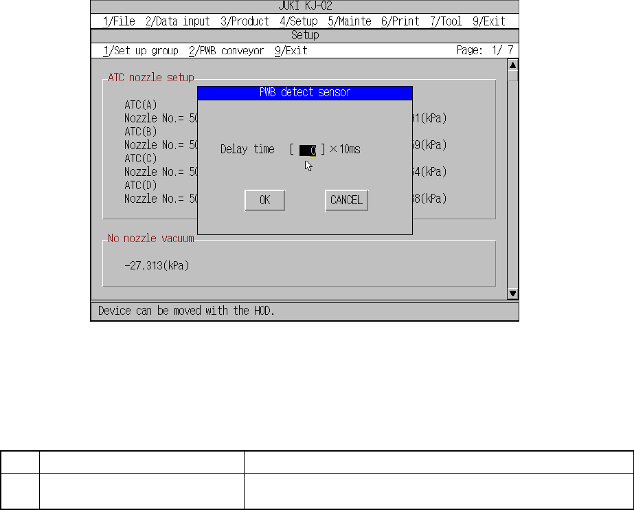
4.3.8 PWB detect sensor
When you select the [8/ PWB detect sensor] command from the [1/Set up group]
menu, the “PWB detect sensor” dialog box appears on the screen as shown in Figure
4.3.8.1.
Figure 4.3.8.1 PWB detect sensor setting dialog box
(1) Setting items
No. Item Description
1 Delay for PWB conveyor sensor Set the delay of the board carriage sensor for the cut out board or
punch hole board.
(2) How to set
① The Delay for conveyor sensor
– This can be set in the range from 0 to 200.
– Unit : ms.