KJ-01.02.Instruction Manual.REV.02.pdf - 第222页
6 − 18 ④ Vision Select the met hod for recognizing a BGA component f r om the menu shown in the f igure below . See T able 6.2. 2.1.4 f or t he meaning of each it em. Figure 6.2. 3.4 BGA recogniti on pattern ty pe settin…
6 − 17
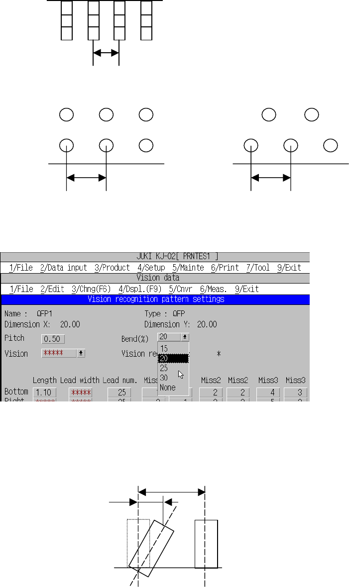
② Pitch
Enter the lead pitch (ball pitch for a BGA component).
a. Lead pitch
b. Ball pitch(Normal assignment) Ball pitch(Stagger assignment)
③ Bend
Select the bending lead detection level from the combo box.
Figure 6.2.3.3 Bent lead detection level setting screen
Bent lead detection level =△L/L
Bent lead detection level definition
Ball
p
itch
L
△L
Ball
p
itch
Lead
p
itch
6 − 18
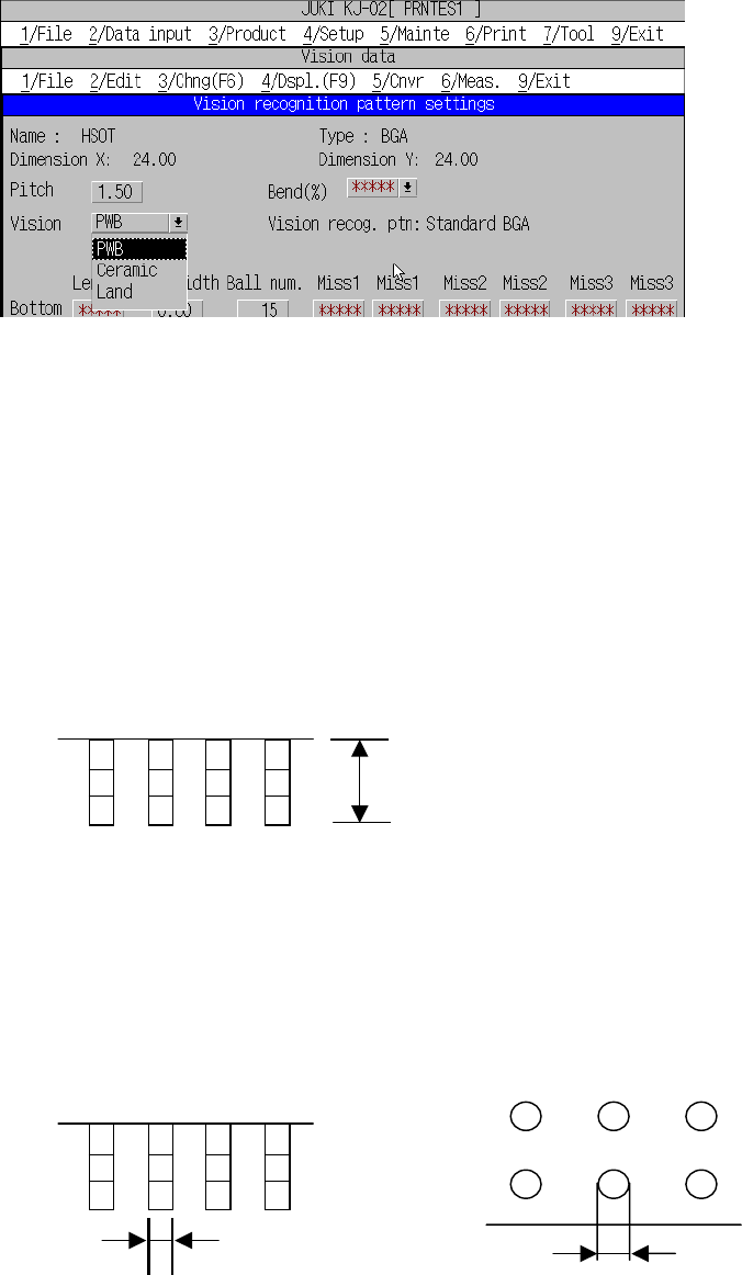
④ Vision
Select the method for recognizing a BGA component from the menu shown in
the figure below. See Table 6.2.2.1.4 for the meaning of each item.
Figure 6.2.3.4 BGA recognition pattern type setting
⑤ Vision recog. ptn (Vision recognition pattern)
The machine displays the pattern for recognizing a
BGA/FBGA/connector/outline-to-be-recognized component currently set.
⑥ Len Bot. (Lead length for bottom), R, Top, L
Enter the overall length of the lead. If the item appears with asterisk (*), it is not
necessary to enter any value for that item.
- Lead length
⑦ Width Bot. (Lead width for bottom) right, top, and left
Enter the width of the lead (for BGA, it is ball diameter).
If the item appears with asterisk (*), it is not necessary to enter any value for that
item.
a. Lead width b. Ball diameter
Lead width Ball diameter
Lead len
g
th
6 − 19
⑧ Bot., R, Top and L (Number of leads)
Enter the number of leads.
If the item appears with asterisk (*), it is not necessary to enter any value for that
item.
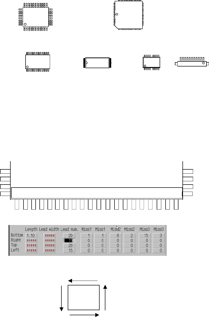
⑨ Miss1 to 3, Miss1 to Miss3, Bottom, Right, Top and Left
The omitted leads are designated by the number of missing leads and their
positions.
Up to 3 blocks of omitted leads can be set per one side. When there is no
omitted leads, set 0/0.
Figure 6.2.3.5 shows the settings when there are omitted leads at the bottom of
the QFP.
<Example> When pins 1, 8, 9, 15, 16, and 17 at the bottom are omitted
Figure 6.2.3.5 Example of lead setting
– Figure 6.2.3.6 shows the order to count the pin numbers.
Figure 6.2.3.6 Counting direction for pin numbers at each side
Top
Left
Bottom
1
Right
Top
Left
Bottom
Right
1
Top
Bottom
1
Left
Right
Top Top
1
1
1 2 3 4 5 6 7 8 9 10 11 12 13 14 15 16 17 18 19 20
Enlarged bottom view of QFP
1 pin from pin 1. 2 pins from pin 8. 3 pins from pin 15.
1
1
1
1