KJ-01.02.Instruction Manual.REV.02.pdf - 第165页
5 − 69 ⑦ Pick ing Z up Using t his f loating menu, set the acceler ation (f or preventing the components f rom dr opping) of Z-axis up movement at pick posit ion. The items to be select ed are the same as t hose of t he …
5 − 68
(1) When centering a component with the laser
① Retry times
Using the formula bar, enter the number of retries. When set with 0, retry is
not performed. The yellow signal light flashes to warn you when an overretry
occurs in production.
② Placing stroke
Using the formula bar, enter the placing stroke for the components to be
mounted. The acceptable input range is 0.0 mm to 4.0 mm.
Set this value rather a large one to fit the components to the bond or solder
when the amount of bond is little too much or of solder is little too thick. Set
this value rather a small one if too much placing stroke is applied resulting in
component bounding on some board.
③ Picking stroke
Using the formula bar, enter how much pick stroke to be applied to the
nozzle when a component is picked. The acceptable input range is 0.0 mm
to 4.0 mm.
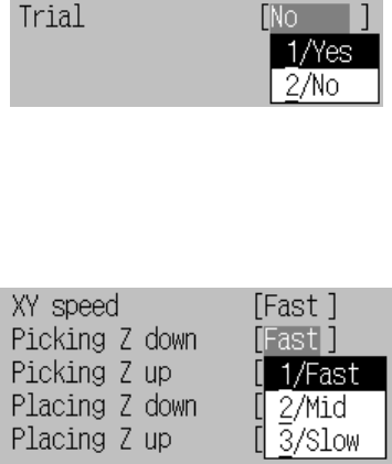
④ Trial
Set in the floating menu whether or not the component is actually placed for
trial.
Figure of Trial setting
⑤ XY speed
Set in the floating menu the accelerations of X and Y to move the
component to the placement position after it is picked.
Figure of XY speed setting
⑥ Picking Z down
Using this floating menu, set the acceleration (for adjusting the stress to the
components) of Z-axis down movement at placement position. The items to
be selected are the same as those of the XY speed above.
For the boards such as ceramic boards which is severe to shock, this item is
adjusted. This can also be used for stress adjustment of the components in
vertical direction.
5 − 69
⑦ Picking Z up
Using this floating menu, set the acceleration (for preventing the
components from dropping) of Z-axis up movement at pick position. The
items to be selected are the same as those of the XY speed above.
⑧ Placing Z down
Using this floating menu, set the acceleration (for preventing the
components from unsteady placement) of Z-axis down movement at pick
position. The items to be selected are the same as those of the XY speed
above.
For very small chips fed from a tape feeder, designate Mid. or Slow if
components are not steady placed.
This can also be used for stress adjustment of the components in vertical
direction.
⑨ Placing Z up
Using this floating menu, set the acceleration (for preventing the
components from being picked up) of Z-axis up movement at placement
position. The items to be selected are the same as those of the XY speed
above.
⑩ Theta speed
Using the floating menu, set the θ rotation speed (for preventing the
component from being shifted) of all rotating operations except rotation for
the LA measurement while the head is waiting for a component. The items to
be selected are the same as those of the XY speed above.
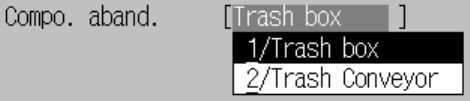
⑪ Compo abandonment
Using the floating menu, set where to discard a component.
− Trash Box : Discards a component into the trash box.
− Trash conveyor : Discards a component onto the IC collection belt.
Select this setting mainly for the IC component type.
Figure of Compo abandonment setting
⑫ Placing offset (X, Y)
Using the formula bar, enter the placement offset for unsymmetric
components whose center of the dimensions differ from the pick point of the
nozzle.
⑬ Laser height
Enter the offset from the surface of the component to the laser using the
formula bar.
This shall be adjusted for the components of not ordinary shape.
For details, see Chapter 1 “GENERAL”.
5 − 70
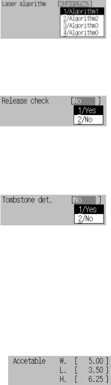
⑭ Laser algorithm
Select the algorithm for laser recognition in the floating menu.
Figure of Laser algorithm setting
⑮ Release check
Using the floating menu, set whether to check to see if a component is stuck
even after it is placed with an LA when an LA centering component is
placed.
Figure of Release check setting
⑯ Tombstone detection
Using the floating menu, select whether to detect chip rise. When you select
“Yes”, the reference value is calculated from the dimensions of a component,
then the default reference value is automatically set. If you change the
dimensions of a component, the default reference value is recalculated.
Figure of Tombstone detection setting
A) Reference value (Width)
Using the formula bar, you can change the dimensions (width and length)
which are used to decide whether a component rise occurs. The entry
range is from 0 to the width/length/height multiplied with 2.
B) Reference value (Length)
Using the formula bar, you can change the dimensions (width and length)
which are used to decide whether a component rise occurs. The entry
range is from 0 to the width/length/height multiplied with 2.
C) Reference value (Height)
Using the formula bar, you can change the dimensions (height) which is
used to decide whether a component rise occurs. The entry range is from
0 to the width/length/height multiplied with 2.
Figure of Reference value setting