KJ-01.02.Instruction Manual.REV.02.pdf - 第204页
5 − 108 W hen y ou click the <No> but ton on the nozzle change quest ion message, t he measurement result is stor ed to Component dat a without changing the current nozzle. If you have checked the check box “Ref le…
5 − 107
5.7.2.7 Finishing measurements
When you click the <OK> button or <CANCEL> button on the “Measurement”
conditions setting screen, the machine finishes measuring a component, and the
head moves to the waiting position.
− When you click the <OK> button
The machine stores the obtained component measurement result to the
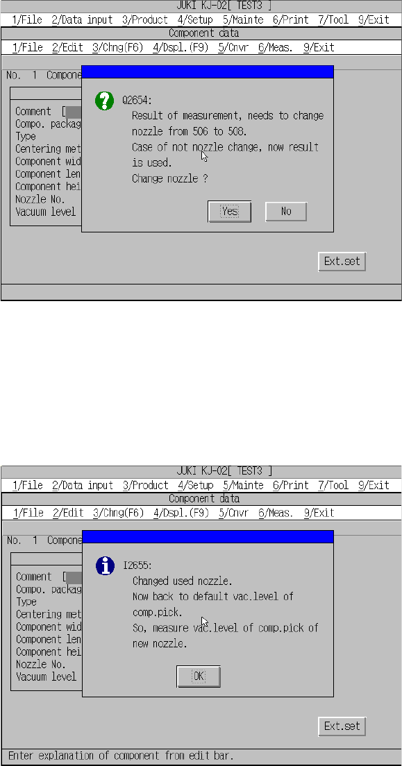
Component data. At this point, the machine may display the question message
that asks you to change a nozzle depending on the measured dimensions of the
component.
Figure Change nozzle question message
When you click the <Yes> button on the question message above, the nozzle
change confirmation screen appears, and the nozzle appropriate to the measured
component is selected. Note that the component pick-up vacuum pressure is reset
to the default value at this point.
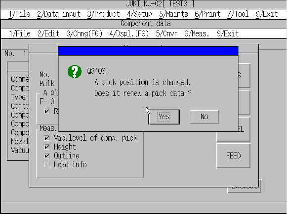
When you click the <OK> button on this confirmation message screen, the
Component data screen reappears. Measure the component again.
Change nozzle confirmation screen
5 − 108
When you click the <No> button on the nozzle change question message, the
measurement result is stored to Component data without changing the current
nozzle.
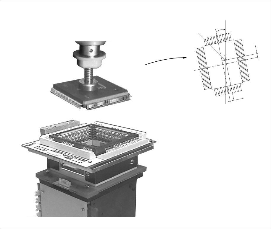
If you have checked the check box “Reflects to the pick data” and changed the
component pick-up position, the machine displays the pick-up position change
confirmation dialog box. Select whether the changed pick-up position is valid or
not.
When you select it, the Component data screen reappears.
Pick-up position change confirmation dialog box
− When you click the <CANCEL> button
The obtained measurement result becomes invalid, and the Component data
screen reappears.
6 − 1
CHAPTER 6 VISION RECOGNITION (KJ-02)
6.1 Position of components for vision recognition
Using the VCS camera, view the position of the component picked up with the vision
correction head to obtain the balance and angle offset of the component. At this time,
component’s bent leads are also checked as faulty. After moving to the PWB
placement point, the obtained balance and angle offsets are corrected for placement at
right balance and angle.
Center of the nozzle
θ
∆Y
∆X