KJ-01.02.Instruction Manual.REV.02.pdf - 第80页
4 − 9 (3) Saving the setting s Althoug h push buttons “ OK” and “ Cancel” are available with each setting g roup, pressing t he OK button will not save the data t o the Flash memo ry . If [9/ Exit] is selected f rom [ 9/…
4 − 8
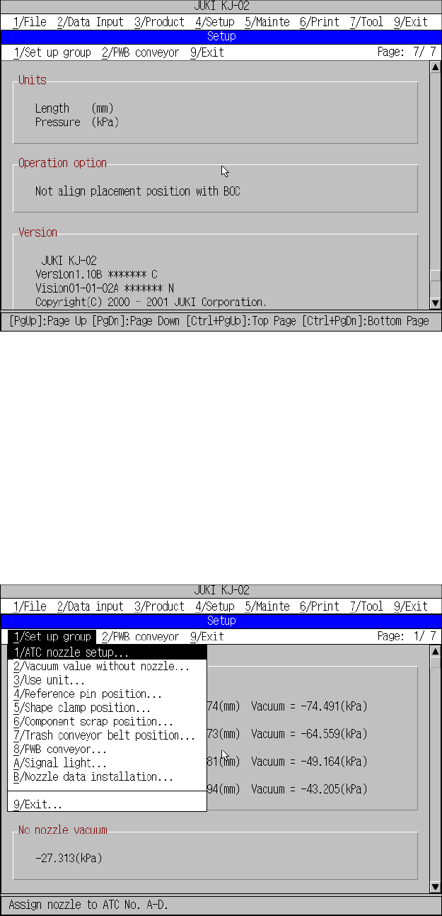
Figure 4.3.8 Machine setup initial screen (8)
To change the setting of each item, select [1/ Set up] of the menu bar.
The units for length and pressure are the parameters set with [1/ Units of measure] of
[4/ Setup].
The initial screen reappears when you press the OK button after having set
parameters with [1/ Setup Group].
(2) The available commands are pulled down when [1/ Setup group] is selected from
the menu bar.
Figure 4.3.9 Setup group commands
During command selection from the machine setup group, the command
summary will not appear on the message line.
Current setting for
[Units],
[Operation opton],
[Version].
4 − 9
(3) Saving the settings
Although push buttons “OK” and “Cancel” are available with each setting group,
pressing the OK button will not save the data to the Flash memory.
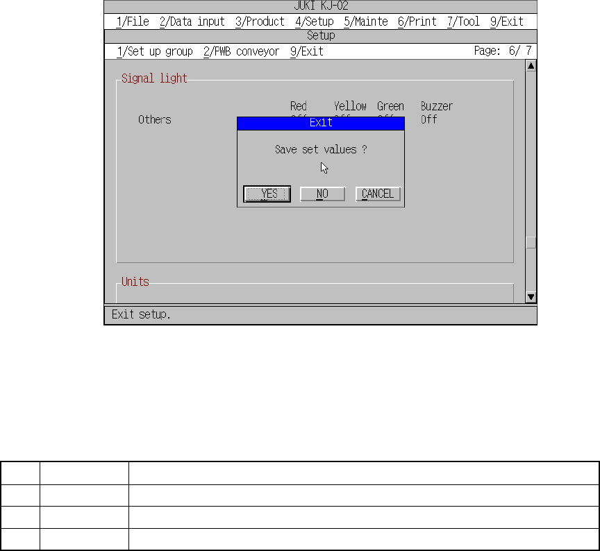
If [9/ Exit] is selected from [9/ Exit] displayed on the menu bar, or if [9/ Exit] is
selected from the [1/ Set up group] menu, a dialog box appears asking you
whether you save the settings or not. The setting data is saved to the Flash
memory if you answer “Yes”.
Figure 4.3.10 Save confirmation screen
Table 4.3.2 Save confirmation buttons
No. Button
Effect
1 Yes Saves the setting data to the Flash memory and quits the machine setup mode.
2 No Cancels the setting data and quits the machine setup mode.
3 Cancel Cancels the exit command.
4 − 10
4.3.1 ATC nozzle setup
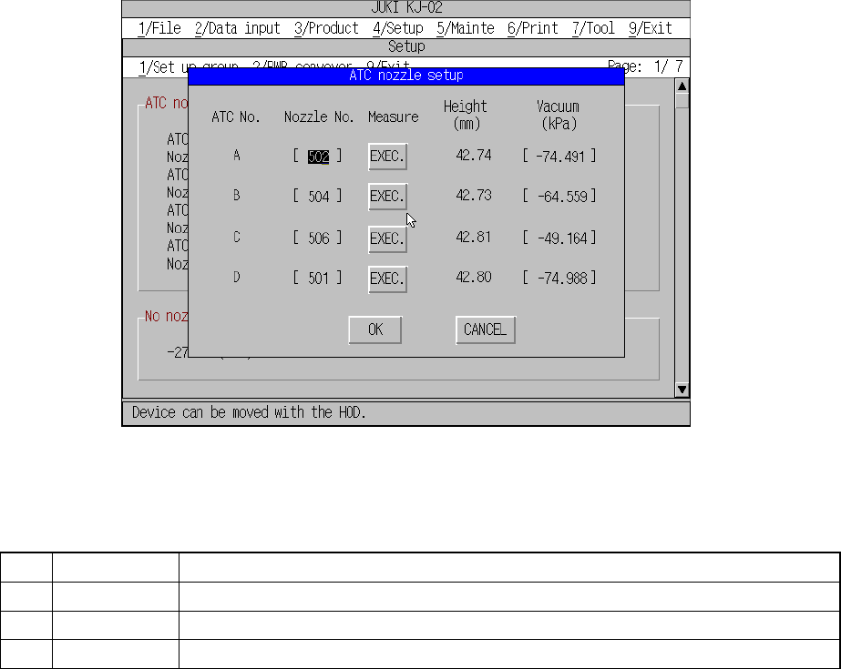
When you select the [1/ ATC nozzle setup] command from the [1/Set up group]
menu, the “ATC nozzle setup” dialog box appears on the screen as shown in
Figure 4.3.1.1.
Figure 4.3.1.1 ATC nozzle setup dialog box
No. Item Description
1 Nozzle number Nozzle number to be allocated to ATC
2 Vacuum value The vacuum value with the nozzle attached (for automatic operation only)
3 Nozzle height The offset of length with respect to the standard nozzle (for automatic operation only)
(1) Setting items
① Setting the nozzle no.
– A character displayed under “ATC No.” indicates the number assigned to
the ATC. Enter the number of a nozzle you want to assign to the ATC.
– You can set a value to the nozzle number on which the input focus is
located. Validate your entering data with pressing the ENTER key or filed
selection key.
– Eight nozzle numbers, 501, 502, 503, 504, 505, 506, 507 and 508 can be
entered as a nozzle number at the initial sate. When you install a new
nozzle with following the procedure described at Section 4.3.10 “Nozzle
data installation,” you can enter the number of the new nozzle here.
– When you erase the entered character(s) with the Delete key or back
space key, or with the space key in Overwrite mode, and then validate
your erasing data with the ENTER key or filed selection key, the
corresponding nozzle is released and the data displayed as “Vacuum” is
cleared.