KJ-01.02.Instruction Manual.REV.02.pdf - 第273页
8 − 6 5) Clamp a working PW B w ith the pusher Y , and adjust t he clamping st rengt h with the reducing valve ⑮ . For a thin and light -weighted board or f ragile ceramic board, set 0.2 Mpa as a guideline. For other t y…
8 − 5
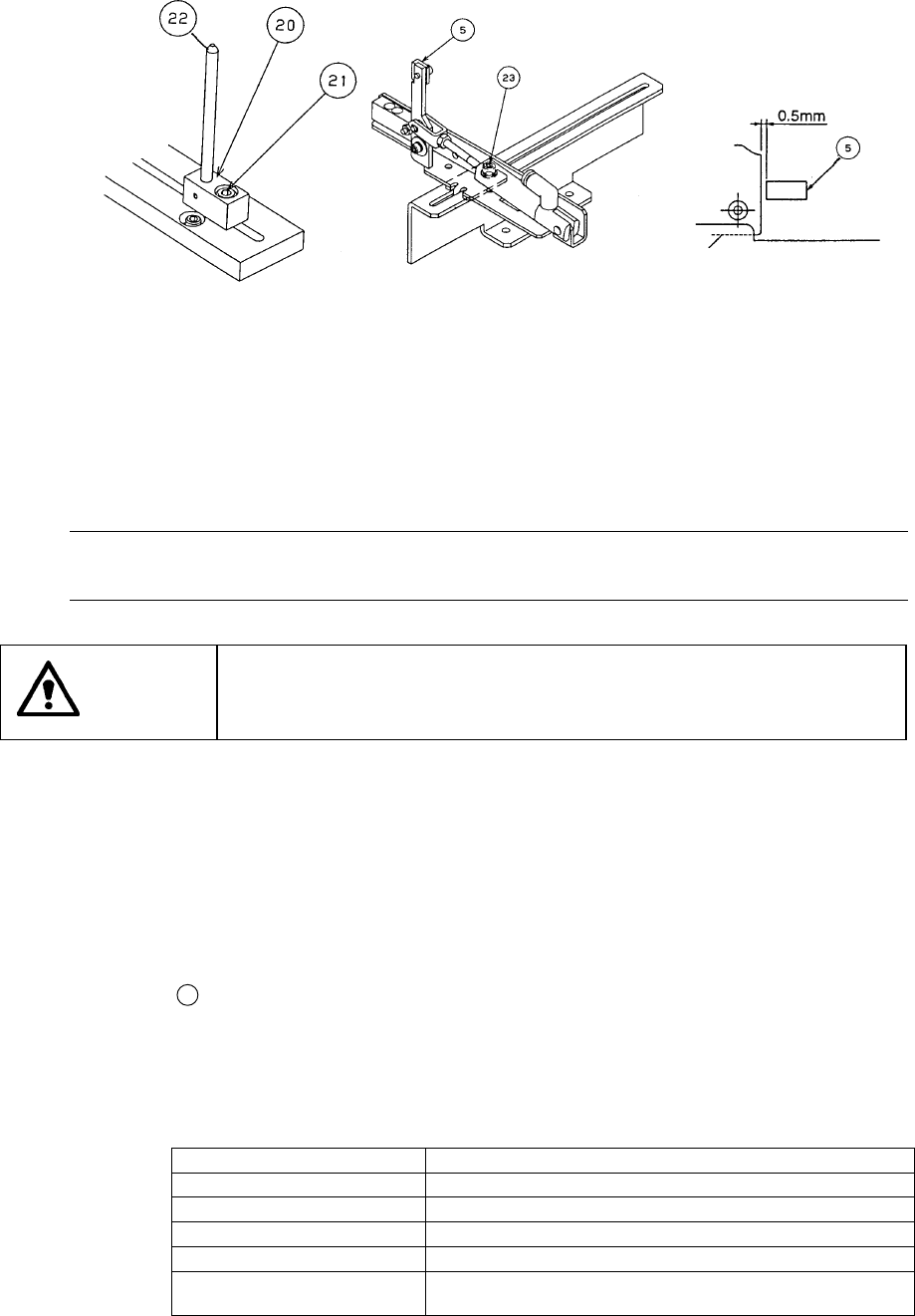
Figure 8.1.3.2 Figure 8.1.3.3 Figure 8.1.3.4
(3) Setting the BU pin
1) Set the BU (back up) pins (two) 9 on the BU plate 7 according to the size of
a PWB to be produced.
2) When components are located on the rear of a PWB, be sure to avoid
components to set the BU pins.
Note: If you set the BU pin under a component that requires precise placement such
as a QFP, the higher accuracy can be achieved.
WARNING
To prevent the body from injury that can be caused by accidental
activation of the machine, turn off the power of the machine before
starting to work.
(4) Adjusting the shape reference position (unnecessary when you select “Hole
reference” as “Reference” on the PWB data screen) (See Figures 8.1.3.3 and
8.1.3.5.)
1) Turn off the main unit power, and also turn off the air valve.
2) Since the centering pin is not used, remove it or slide it in the X direction so
that it can be moved outside the board.
3) Using the supplied ball driver, loosen the M4 hexagonal-hole-headed bolt
23
that fixes the stopper ⑤, and adjust the stopper position so that it
cannot be located around the center or any cutout of a board.
4) Turn on the air valve, and operate the solenoid valve ⑱ located on the
right bottom corner of the electrical section to move the pusher Y.
Each solenoid setting is shown below:
Solenoid valve setting Description
ATC Opens/closes the ATC sliding plate.
CAL Operates the vacuum generator for the CAL block.
SHA Operates the pusher Y (of the PWB transport section
STO Operates the stopper (of the PWB transport section).
BU Moves the BU plate up/down (of the PWB transport
section).
When you push the manual switch ⑲ of the solenoid valve, it starts operating.
When you turn this switch clockwise while it is depressed, the current setting is
held.
PWB
8 − 6
5) Clamp a working PWB with the pusher Y, and adjust the clamping strength
with the reducing valve ⑮. For a thin and light-weighted board or fragile
ceramic board, set 0.2 Mpa as a guideline. For other type of boards,
adjust the strength with setting 0.3 Mpa to 0.4 Mpa as a guideline.
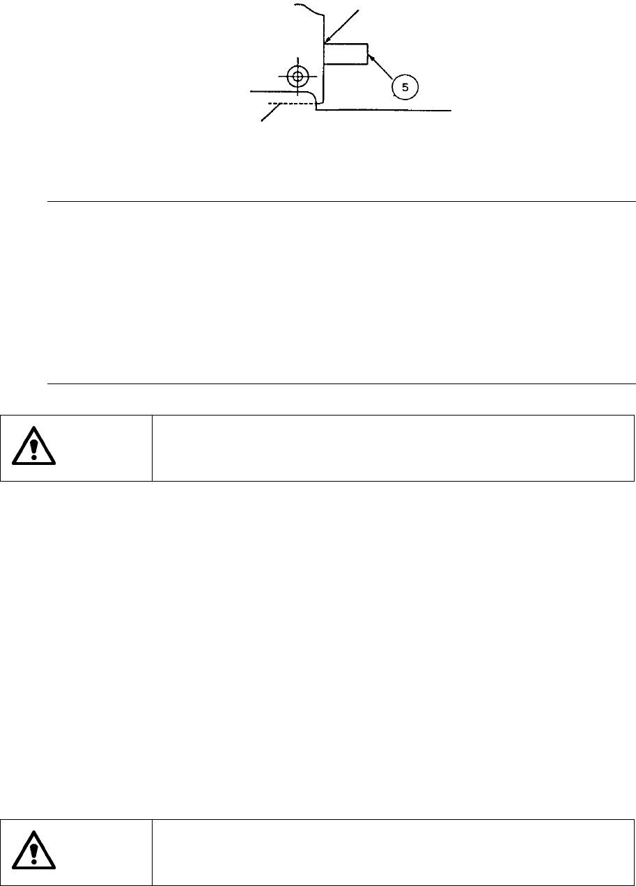
Figure 8.1.3.5
Notes:
①
You can adjust the shape reference position by using the [3/Conveyor]
command on the menu bar, and then the [1/Conveyor control] command
when the machine is turned off and the air valve is turned off also (see
Chapter 9, “I/O MANUAL CONTROL”).
②
When you move the stopper, be sure to re-enter the shape reference
position on the Machine Setup menu. Otherwise, the reference position
of the data is set differently.
③
When you transport a PWB whose specifications are the same, you do
not have to make any adjustment.
WARNING
To prevent the body from injury that can be caused by accidental
activation of the machine, turn off the power of the machine before
starting to work.
(5) Entering the position of the centering pin (skip this step when the board outline
is used for reference)
1) Turn on the power of the machine, and also turn on the air valve.
Perform zeroing (origin setting).
2) Select the [4/Setup] command on the menu bar, and the [3/Machine setup]
command on the displayed “Setup” menu. Select the [1/Set up group]
command, and the [4/Reference pin position] command on the “Set up
group” menu.
3) Click the <Support plate ON/OFF> button on the “Reference pin position”
dialog box to move up the support plate.
4) Move the input focus to the “X” or “Y” column, and press the CAMERA key
of the HOD. The OCC moves above the centering pin.
5) While viewing the vision monitor, teach the center of the centering pin.
(See Section 4.3.4 of “Machine Setup”.)
WARNING
To avoid a risk of injury, do not place your hand in the machine, nor
move your face or head close to the machine during operation of the
HOD.
Contact
Board

8 − 7
(6) Entering positions for the use of Board outline reference
(skip this step for the use of pin reference)
1) Turn off the machine, and also turn off the air valve. Initialize the machine
(return each axis to its home position).
2) Select the [4/Setup] command on the menu bar, and the [3/Machine setup]
command on the displayed “Setup” menu. Select the [1/Set up group]
command, and the [5/Shape clamp position] command on the “Set up
group” menu.
3) Click the <Stopper pin ON/OFF> button on the “Shape clamp position”
dialog box to raise the stopper.
4) Set a board on the board transfer rails, then push it against the stopper ⑨
lightly.
5) Move the input focus to the “X” column, then press the [CAMERA] key of
the HOD. The OCC camera moves to the current outline reference
position.
6) While viewing the vision monitor, align the crosshair cursor with the outline
of the PWB (X direction), and press the ENTER key. Only a value of the
X coordinate is entered. Note that the PWB should be in contact with the
PWB guide and the stopper.
7) Align the cursor with the Y window, then press the [CAMERA] key of the
HOD. The OCC camera returns to the outline reference position.
8) While viewing the vision monitor, align the crosshair cursor with the outline
of the PWB (Y direction), and press the ENTER key. Only a value of the
Y coordinate is entered. Note that the PWB should be in contact with the
PWB guide. (See Section 4.3.5 of “Machine Setup.”)
WARNING
To avoid a risk of injury, do not place your hand in the machine, nor
move your face or head close to the machine during operation of the
HOD.