KJ-01.02.Instruction Manual.REV.02.pdf - 第145页
5 − 49 Figure 5.5. 1.6 Component ty pe setting screen ④ Centering method W hen you move the cursor to t his item, t he centering method list box appears on the screen as shown in Figure 5.5. 1.7. Select an appropr iate c…
5 − 48
− When [3/ Tray] is selected
Figure 5.5.1.5 Screen after [3/ Tray] has been selected
* If you select “Stick” or “Bulk,” this window does not open.
③ Type
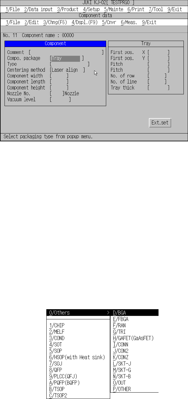
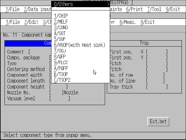
When you move the cursor to this item, the component type list box appears on
the screen as shown in Figure 5.5.1.6. Select an appropriate one from this list
box.
− When you select CHIP, MELF, SOT, RAN or TRI, the item “Centering
method” is set to “Laser align” since those components are to be centered
with laser only.
− When you select FBGA or GaAsFET, the item “Centering method” is set to
“VCS” since those components are to be centered with a VCS only.
* KJ-01 does not allow you to select “VCS” as the centering method, or
select a component centered with the VCS as a component type.
− When you select “OTHER”, the following sub-list box appears on the screen.
“Others” sub-list box
The “Tray”
window opens
when [3/Tray]
is selected.
5 − 49
Figure 5.5.1.6 Component type setting screen
④ Centering method
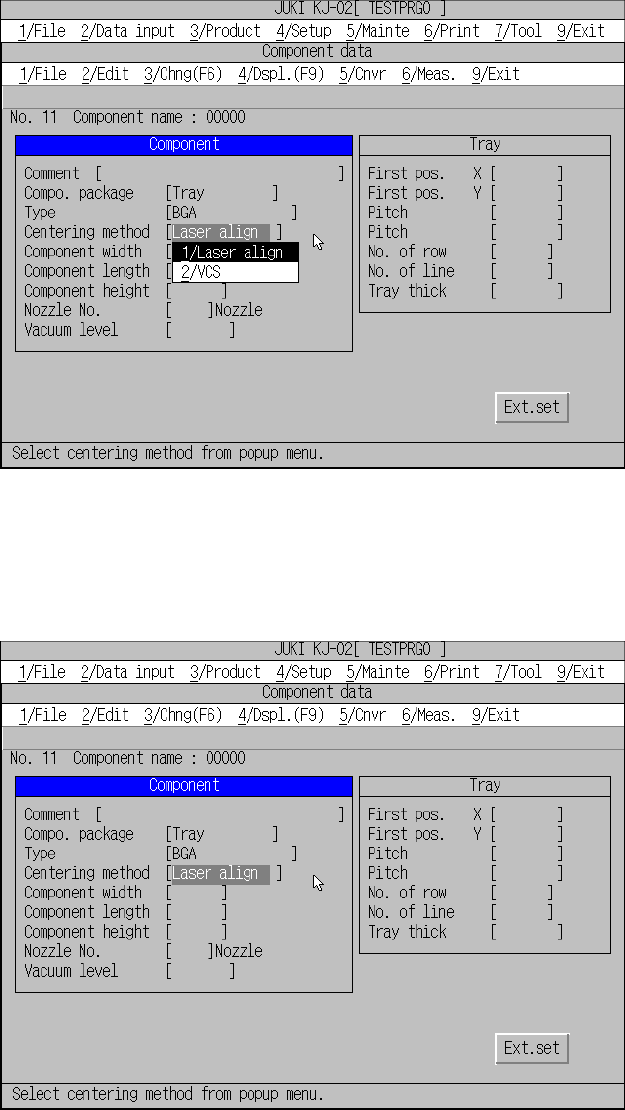
When you move the cursor to this item, the centering method list box appears on
the screen as shown in Figure 5.5.1.7. Select an appropriate centering method,
“Laser align” or “VCS.”
When you do not select any of the following component types, you cannot select
“VCS” here:
SOP, QFP, PQFP, TSOP, TSOP2, BGA, FBGA, SOP (with heat sink), SOJ,
PLCC, unidirectional lead connector, bi-directional lead connector, Z-lead
connector, J-lead socket, gull-wing socket, socket with a bumper, GaAsFET,
aluminum electrolytic capacitor and outline-to-be-recognized component.
Select a
component type.
5 − 50
Figure 5.5.1.7 Centering method setting screen
− When [1/Laser align] is selected
Figure 5.5.1.8 Screen displayed after you select “Laser align”