KJ-01.02.Instruction Manual.REV.02.pdf - 第271页
8 − 4 8.1.3.2 Basi c adjustment s (1) Adj usting t he distance of the PW B transport r ails W hen you change the size of a PW B, move the PW B transport R unit 16 back and for th to adj ust the distance of rails accor di…
8 − 3
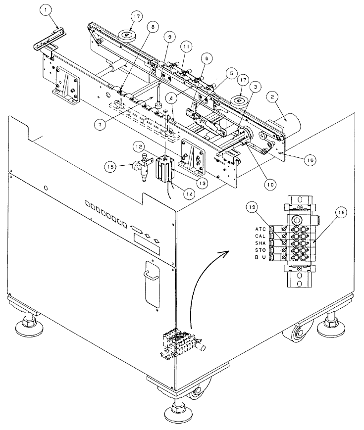
8.1.3 Preparation of PWB transport section
8.1.3.1 Entire view of PWB transport section
① IN sensor ⑪ Pusher Y
② PWB transport motor ⑫ BU cylinder
③ Drive shaft ⑬ BU-UP sensor
④ PWB transport belt ⑭ BU-DOWN sensor
⑤ Stopper ⑮ Depressure valve (Edge reference option)
⑥ STOP sensor ⑯ PWB transport rail R unit
⑦ BU Plate ⑰ Rail keeping knob
⑧ Centering pin ⑱ Solenoid valve
⑨ BU pin ⑲ Manual switch
⑩ OUT sensor
Figure 8.1.3.1
8 − 4
8.1.3.2 Basic adjustments
(1) Adjusting the distance of the PWB transport rails
When you change the size of a PWB, move the PWB transport R unit 16 back
and forth to adjust the distance of rails according to the size of a PWB. First
of all, loosen the rail keeping knobs 17 (two), and then fix them after adjusting
them according to the PWB width. Check to see if a PWB can be transported
smoothly from the entrance of the PWB transport device to the exit. Allow a
0.5-mm space between a PWB and the rails. After adjustments, check to see
if a PWB is transported smoothly through the PWB transport section of the
machine.
WARNING
To prevent the body from injury that can be caused by accidental
activation of the machine, turn off the power of the machine before
starting to work.
(2) Adjusting the centering pin (unnecessary when you select “Shape Reference”
as “Reference” on the PWB data screen)
(See Figures 7.1.3.2, 7.1.3.3 and 7.1.3.4.)
1) Turn off the main unit power, and also turn off the air valve.
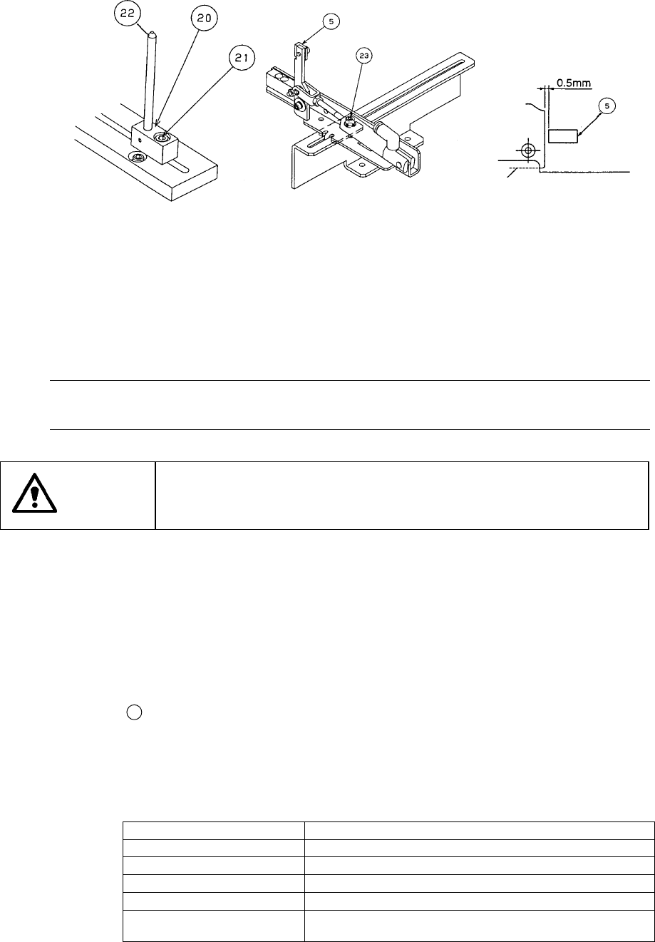
2) Using the supplied ball driver, loosen the M4 hexagonal-hole-headed bolt
21
that fixes the guide block
20
.
3) Using the supplied ball driver, loosen the M4 hexagonal-hole-headed bolt
23
that fixes the stopper ⑤, and adjust the stopper position so that it
cannot be located around the center or any cutout of the board.
4) Slide the guide block
20
in the X direction, and fit the centering pin
22
with the reference hole of the board. Be sure to allow a 0.5-mm space
between the stopper and the board. If this space is too small, the board
may not be set with ease.
Notes:
①
You can adjust the centering pin by using the [3/Conveyor] command
on the menu bar, then the [1/Conveyor control] command when the
machine is turned off and the air valve is turned off also (see Chapter
9, “I/O MANUAL CONTROL”).
②
When you move the centering pin, be sure to re-enter the reference
pin position on the Machine Setup menu. Otherwise, the reference
position of the data is set differently.
③
When you transport a board whose specifications are the same, you
do not have to adjust the centering pin.
WARNING
To prevent the body from injury that can be caused by accidental
activation of the machine, turn off the power of the machine before
starting to work.
8 − 5
Figure 8.1.3.2 Figure 8.1.3.3 Figure 8.1.3.4
(3) Setting the BU pin
1) Set the BU (back up) pins (two) 9 on the BU plate 7 according to the size of
a PWB to be produced.
2) When components are located on the rear of a PWB, be sure to avoid
components to set the BU pins.
Note: If you set the BU pin under a component that requires precise placement such
as a QFP, the higher accuracy can be achieved.
WARNING
To prevent the body from injury that can be caused by accidental
activation of the machine, turn off the power of the machine before
starting to work.
(4) Adjusting the shape reference position (unnecessary when you select “Hole
reference” as “Reference” on the PWB data screen) (See Figures 8.1.3.3 and
8.1.3.5.)
1) Turn off the main unit power, and also turn off the air valve.
2) Since the centering pin is not used, remove it or slide it in the X direction so
that it can be moved outside the board.
3) Using the supplied ball driver, loosen the M4 hexagonal-hole-headed bolt
23
that fixes the stopper ⑤, and adjust the stopper position so that it
cannot be located around the center or any cutout of a board.
4) Turn on the air valve, and operate the solenoid valve ⑱ located on the
right bottom corner of the electrical section to move the pusher Y.
Each solenoid setting is shown below:
Solenoid valve setting Description
ATC Opens/closes the ATC sliding plate.
CAL Operates the vacuum generator for the CAL block.
SHA Operates the pusher Y (of the PWB transport section
STO Operates the stopper (of the PWB transport section).
BU Moves the BU plate up/down (of the PWB transport
section).
When you push the manual switch ⑲ of the solenoid valve, it starts operating.
When you turn this switch clockwise while it is depressed, the current setting is
held.
PWB