KJ-01.02.Instruction Manual.REV.02.pdf - 第369页
13 − 7 <Procedure for setting t he sensitivity of the bad mark sensor> 1. Set t he Mode sw itch t o “SET”. “1” appears on the dig ital display . 2. Alig n the red spot of a bad m ark with a mar k of a board. 3. Pre…
13 − 6
13.5 Handling the Bad Mark Sensor
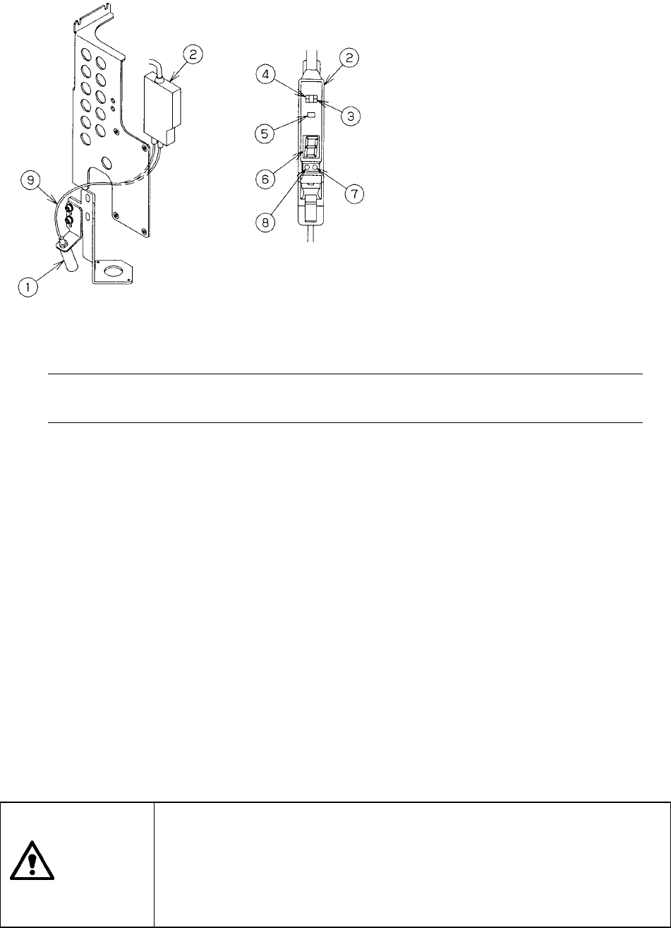
Figure 13.5.1
Note: Do not change the setting of the L-ON/D-ON switch (setting at the factory:
D-ON).
1) Color and size of a bad mark
a) A bad mark on a PC board to which green resist is applied shall be a glossy
white mark of 2.5 mm in diameter or greater.
b) A bad mark on a white ceramic PC board shall be a black mark of 2.5 mm in
diameter or greater.
c) The bad-mark reader cannot recognize the smaller or faded marks. The bad
marks shall be clear and legible.
2) How to set the sensitivity of the bad mark sensor
− Since the sensitivity of the bad mark sensor is set at the factory, do not touch
the mode switch or tuning button easily.
− The bad mark sensor cannot detect a bad mark easily depending on the color
of a board or mark. In such a case, set the sensitivity of the bad mark sensor
as described in the following procedure.
CAUTION
To avoid risk of injury, set the sensitivity of the bad mark sensor only after
you open the cover, and check to see if the main unit comes to halt
completely.
Be carefully to attach the bad mark sensor on the machine so that any
wrong operation of a person working an internal part cannot cause the
machine to start up unexpectedly.
① Detecting head
② Bad mark sensor amplifier
③ Mode switch
④ L-ON/D-ON switch
(decides whether the sensor is
turned ON when receiving light or
when shutting light).
⑤Auto tuning button
⑥Digital display
⑦Stability light (green)
⑧Operation light (red)
⑨Fiber
13 − 7
<Procedure for setting the sensitivity of the bad mark sensor>
1. Set the Mode switch to “SET”. “1” appears on the digital display.
2. Align the red spot of a bad mark with a mark of a board.
3. Press the tuning button once.
“2” appears on the digital display.
Check to see if only the green LED flashes.
4. Move the red spot of the bad mark outside a mark of the board.
5. Press the tuning button once.
A value from “1” to “9” (detection margin) appears on the digital display.
Check to see if the green LED lights up.
6. Set the Mode switch to “RUN.”
A value from “1” to “9” (received light level) appears on the digital display.
The following two types errors may occur.
If an error occurs, set the sensitivity of the bad mark sensor again.
1. Insufficient sensitivity: ..........The red LED flashes (green LED goes off), and “E”
flashes on the digital display. Note that the red and
green LEDs flash and “2” appears on the digital
display at Step 3.
2. Insufficient level difference: .The red LED lights up (green LED goes off), and “E”
appears on the digital display.
14 − 1
CHAPTER 14 MAINTENANCE
14.1 Daily Routine Checks
14.1.1 List of daily routine checks
CAUTION
To prevent the body from injury which can be caused by accidental
activation of the machine, cut off the power to the machine before starting
to work.
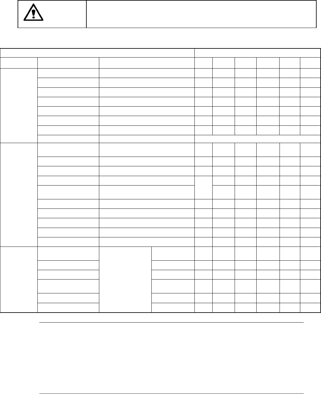
Table 14.1.1
Items to be checkedk
Check and lubrication frequency
Maintenance
Check point
Check
Daily
Weekly
Monthly
Bimonthly
Every
half year
Every
year
Air pressure Check 0.49 MPa (5kgf/cm2).
○
Piping and joint Air leakage
○
Unit air cylinder Check operation.
○
Air filter (Head) No dirt
○
Power on lamp Check if it is lit.
○
Transfer belt Worn out, damage, or stretch
○
Transfer pulley If it functions properly.
○
Check
Electric device Voltage, cables, and connectors Whenever necessary
X- and Y-axis direct
drive units
Remove dirt and oil.
○
Transfer belt Remove dirt and foreign substances
○
Transfer sensors Cleaning
○
Laser align sensor Cleaning of the sensor window
○
Nozzle
Disassemble and cleaning inside the
nozzle
○
ATC bracket Remove dirt and oil.
○
Feeder bank Remove foreign substances.
○
Z slide shaft Cleaning inside the shaft.
○
OCC (Polarizing filter) C Remove dirt and foreign substances.
○
Cleaning
Track ball C Remove dirt and foreign substances.
○
X- and Y-axis direct
drive unit rails
Grease (EP2)
○
Transfer screw shaft
Grease (EP2)
○
PWB stopper part Grease (EP2)
○
Ball screw and LM guide
rail (Head part)
Grease (AFC)
○
Spline shaft (head part) Grease (AFC)
○
Lubrication
Support table
Smooth movement
Grease (EP2)
○
Notes: 1. Lubrication is to be performed using the supplied oil. Besides the supplied
grease (EP2), SHELL Albania Grease 1 can be used for the parts to be greased
only.
2. Never apply any grease other than grease (Grease C) to the parts to be lubricated
with "Grease (Grease C)". For other parts, do not use any grease not specified
by JUKI.
3. Machine oil (No. 1): Class four, third petroleum
Grease (EP2): Not dangerous product regulated with the Fire-Defense law
Grease (Grease C): Not dangerous product regulated with the Fire-Defense law.