KJ-01.02.Instruction Manual.REV.02.pdf - 第109页
5 − 13 For the basic setup chang e screen, t he following item s are to be ent ered. T o change to another it em, use t he T AB key or the T AB and SHIFT keys. (1) PW B ID Up t o 32 alphanumeric char acters and symbols c…
5 − 12
5.3.2 Basic setting
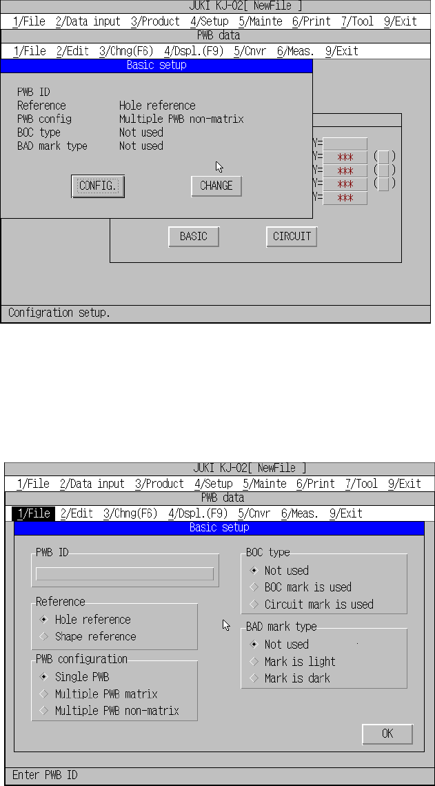
A screen as shown in Figure 5.3.2.1 appears and default setting is listed when the
input focus has been moved to basic setting.
Figure 5.3.2.1 Basic setup screen (Single pattern)
You cannot change the basic settings on this screen. By pressing the Change button,
Basic setup change screen appears as shown in Figure 5.3.2.2, and the basic
settings can be changed there.
Figure 5.3.2.2 Basic setup change screen
5 − 13
For the basic setup change screen, the following items are to be entered. To change
to another item, use the TAB key or the TAB and SHIFT keys.
(1) PWB ID
Up to 32 alphanumeric characters and symbols can be entered. However, note
that only numbers or only symbols cannot be entered. They shall be combined
with alphabetic characters. When reading the production program, the PWB ID is
displayed as well as the file name of the production program, so enter an ID
which is easy to understand.
(2) Reference method
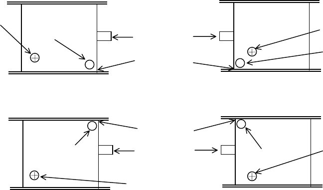
1) Hole reference
The PWB has positioning holes, and the reference pins are inserted in the
holes to hold the PWB.
2) Shape reference
After the PWB touches the stopper, the edges of the PWB are fixed
mechanically to hold the PWB.
①
①①
①
Front reference ②
②②
②
Front reference
③
③③
③
Rear reference ④
④④
④
Rear reference
Figure 5.3.2.3 Positioning hole position and the shape reference position
Board transport direction: from left to right Board transport direction: from l right to left
Origin of a board
Board
Positioning hole
Stopper pin
Shape reference
position
Origin of a board
Positioning hole
Board transport direction: from left to right Board transport direction: from l right to left
Board
Positioning hole
Board
Positioning hole
Origin of a board
Origin of a board
Stopper pin
Shape reference
position
5 − 14
(3) PWB configuration
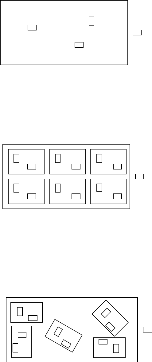
1) Single PWB
The PWB which has only one circuit pattern.
Figure 5.3.2.4 Figure of the single pattern
2) Multiple PWB matrix
The PWB which has multiple circuit patterns aligned in depth and width and
with a same angle and space.
Figure 5.3.2.5 Figure of the Matrix multiple patterns
3) Multiple PWB non-matrix
The PWB which has multiple circuit patterns but with a different angle and
space among them.
Figure 5.3.2.6 Figure of the Non-matrix multiple patterns
Components
Components
Components