KJ-01.02.Instruction Manual.REV.02.pdf - 第166页
5 − 70 ⑭ Laser algorit hm Select t he algorit hm f or laser r ecognition in t he float ing menu. Figure of Laser algorithm setti ng ⑮ Release check Using t he f loating menu, set whether to check to see if a component is…
5 − 69
⑦ Picking Z up
Using this floating menu, set the acceleration (for preventing the
components from dropping) of Z-axis up movement at pick position. The
items to be selected are the same as those of the XY speed above.
⑧ Placing Z down
Using this floating menu, set the acceleration (for preventing the
components from unsteady placement) of Z-axis down movement at pick
position. The items to be selected are the same as those of the XY speed
above.
For very small chips fed from a tape feeder, designate Mid. or Slow if
components are not steady placed.
This can also be used for stress adjustment of the components in vertical
direction.
⑨ Placing Z up
Using this floating menu, set the acceleration (for preventing the
components from being picked up) of Z-axis up movement at placement
position. The items to be selected are the same as those of the XY speed
above.
⑩ Theta speed
Using the floating menu, set the θ rotation speed (for preventing the
component from being shifted) of all rotating operations except rotation for
the LA measurement while the head is waiting for a component. The items to
be selected are the same as those of the XY speed above.
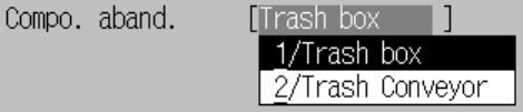
⑪ Compo abandonment
Using the floating menu, set where to discard a component.
− Trash Box : Discards a component into the trash box.
− Trash conveyor : Discards a component onto the IC collection belt.
Select this setting mainly for the IC component type.
Figure of Compo abandonment setting
⑫ Placing offset (X, Y)
Using the formula bar, enter the placement offset for unsymmetric
components whose center of the dimensions differ from the pick point of the
nozzle.
⑬ Laser height
Enter the offset from the surface of the component to the laser using the
formula bar.
This shall be adjusted for the components of not ordinary shape.
For details, see Chapter 1 “GENERAL”.
5 − 70
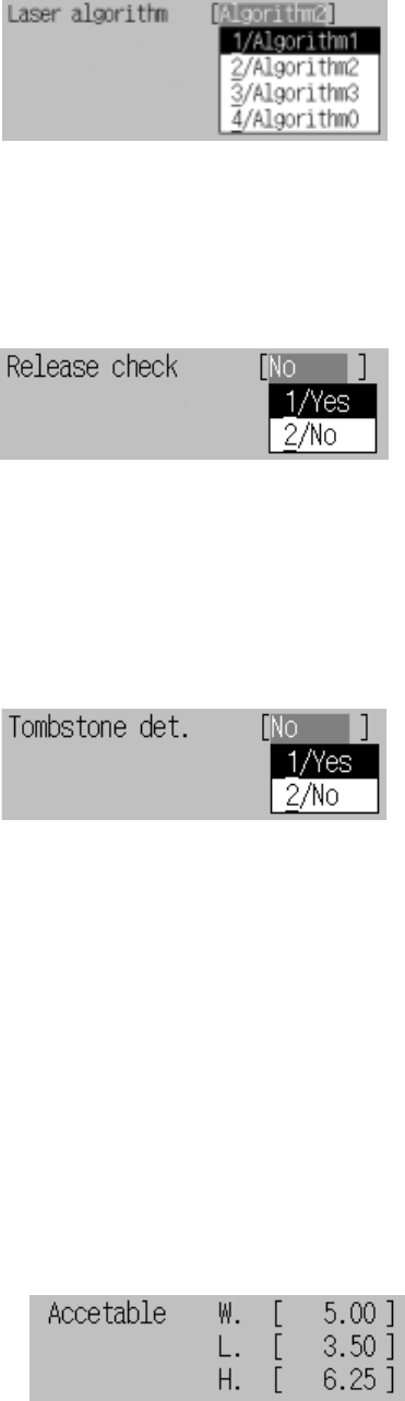
⑭ Laser algorithm
Select the algorithm for laser recognition in the floating menu.
Figure of Laser algorithm setting
⑮ Release check
Using the floating menu, set whether to check to see if a component is stuck
even after it is placed with an LA when an LA centering component is
placed.
Figure of Release check setting
⑯ Tombstone detection
Using the floating menu, select whether to detect chip rise. When you select
“Yes”, the reference value is calculated from the dimensions of a component,
then the default reference value is automatically set. If you change the
dimensions of a component, the default reference value is recalculated.
Figure of Tombstone detection setting
A) Reference value (Width)
Using the formula bar, you can change the dimensions (width and length)
which are used to decide whether a component rise occurs. The entry
range is from 0 to the width/length/height multiplied with 2.
B) Reference value (Length)
Using the formula bar, you can change the dimensions (width and length)
which are used to decide whether a component rise occurs. The entry
range is from 0 to the width/length/height multiplied with 2.
C) Reference value (Height)
Using the formula bar, you can change the dimensions (height) which is
used to decide whether a component rise occurs. The entry range is from
0 to the width/length/height multiplied with 2.
Figure of Reference value setting
5 − 71
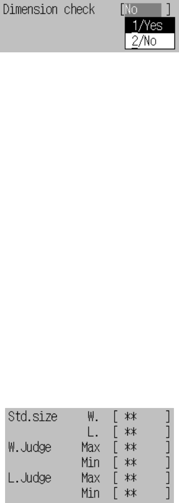
⑰ Dimension check
(* The current version of the machine (1.00) cannot use this function.)
Using the floating menu, select whether to check the dimensions of a
component. When you select “Yes”, the dimensions of a component are
automatically set as the standard dimensions, then the default value. If you
change the dimensions of a component, the default value of the standard
size is reset.
Figure of Dimension check setting
− This inspection is available only if one of the following conditions is
satisfied:
- Components are square chips, Melf, or SOTs.
− Inspection standards
The dimensions limits (upper and lower) of a component (width and
length) are internally calculated with using the following parameters.
When the dimensions exceed the upper limit or lower limit at recognition,
the component error occurs because of a different size of component.
A) Standard size (Width and Length)
Using the formula bar, you can change the component dimensions (width
and length) which is used to decide whether the component dimensions
are appropriate. The entry range is from 0 to the actual dimensions.
B) W. Judge (Max, Min)
Using the formula bar, you can change the ratio to the standard width (Std.
Size W.) in the range from 1 % to 100 %. The smaller value you enter,
the stricter check the machine performs.
C) L. Judge (Max, Min)
Using the formula bar, you can change the ratio to the standard size in
the range from 1 to 100%. Smaller this value is, the stricter inspection is
performed.
Figure of Inspection standards setting