KJ-01.02.Instruction Manual.REV.02.pdf - 第33页
1 − 17 1.2 Basic Configuration and Parts Identification 1.2.1 Entire sy stem v iew s Figure 1.2.1. 1 Figure 1.2.1. 2 ① Signal tower ⑥ Key board ② Vision monitor ⑦ Breaker ③ CRT display ⑧ Filter regulator ④ HOD unit ⑨ Pow…
1 − 16
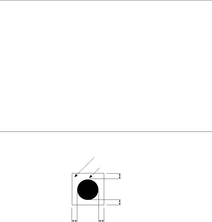
Notes: 1. When recognition, the mark shall be placed in the angle shown above.
However, if you specify "Use of each circuit mark" for a non-matrix
PWB, the mark can be recognized only when all marks of the
reference circuit are positioned in the angle described and the circuit is
positioned at 90, 180, 270 or 360 degrees.
2. The fiducials of the same shape and same size is preferable within a
board.
3. When processing, copper foil or solder plating can be recognized.
4. Maximum number of marks which can be registered
Board mark: 1 set (2 marks or 3 marks)
IC mark: 50 sets (Pairs of 2 marks)
5. Items that can be registered
Mark number
Balance detection window
Normal/reverse rotation identification when detected
Mark shape
Outer dimensions
Figure 1.1.7.3
Clearance area
Recognition mark
0.5 mm or more
0.5 mm or more
0.5 mm or more
1 − 17
1.2 Basic Configuration and Parts Identification
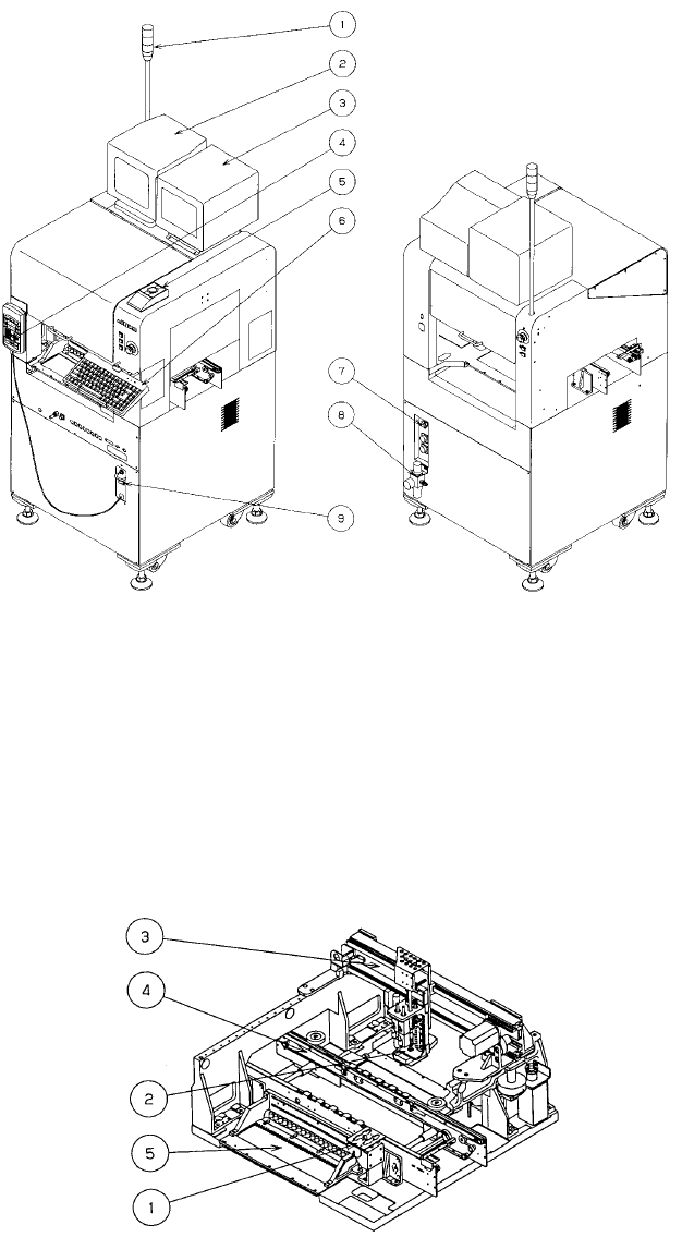
1.2.1 Entire system views
Figure 1.2.1.1 Figure 1.2.1.2
① Signal tower ⑥ Keyboard
② Vision monitor ⑦ Breaker
③ CRT display ⑧ Filter regulator
④ HOD
unit
⑨ Power switch
⑤ Track ball (option)
Figure 1.2.1.3
① ATC unit ⑥ PWB transfer unit
② Head unit ⑦ Feeder bank unit
③ X-Y unit ⑧ VCS
1 − 18
1.2.2 PWB transfer unit: mechanism and parts identification
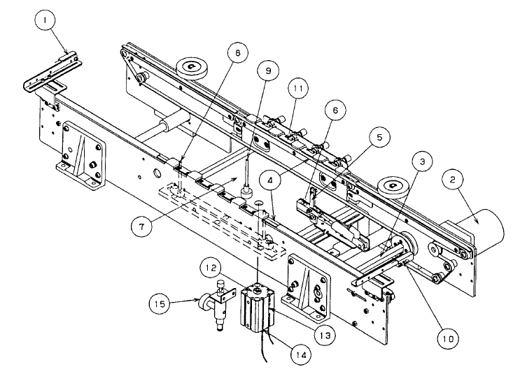
1. Pin reference
When a board is carried in and the IN sensor ① detects the board, the transport
motor ② drives the drive shaft ③ , and the transport belt ④ starts to feed the
board. At the same time, the stopper ⑤ turns on.
When the board reaches the wait stopper ⑤ , the STOP sensor ⑥ detects the
board, and the BU plate ⑦ goes up. At this moment, the board is held by the
transport belt ④, the centering pin ⑧, and the BU pin ⑨
After production finishes, the fixed board is released. When the machine ejects
the board and the OUT sensor ⑩ detects it, the board ejection process finishes.
2. Edge reference <Option>
The board loading mechanism is the same as that of the pin reference above.
When the board is fixed, the pusher Y ⑪ pushes its edges against the fixed rail
side so that the board can be positioned. Then the board is fixed with the PWB
transport belt ④ and BU pin ⑨.
The transport operation that follows is also the same as the pin reference above.
① IN sensor ⑨ BU Pin
② PWB transport motor ⑩ OUT sensor
③ Drive shaft ⑪ Pusher Y
④ PWB transport belt ⑫ BU cylinder
⑤ Stopper ⑬ BU-UP sensor
⑥ STOP sensor ⑭ BU-DOWN sensor
⑦ BU plate ⑮ Depressure valve (Edge reference option)
⑧Centering pin