KJ-01.02.Instruction Manual.REV.02.pdf - 第229页
6 − 25 ⑧ Components whose side roughness for ming a linear por tion is 0.1 mm or less Fig. 6.4. 2.4 Explanatory Draw ing of Recogniti on Condition ⑧ W hen the abov e recog nition conditions are sat isfied, corner r ecogn…
6 − 24
6.4.2 Limitation on components depending on the recognition method
(1) Corner recognition
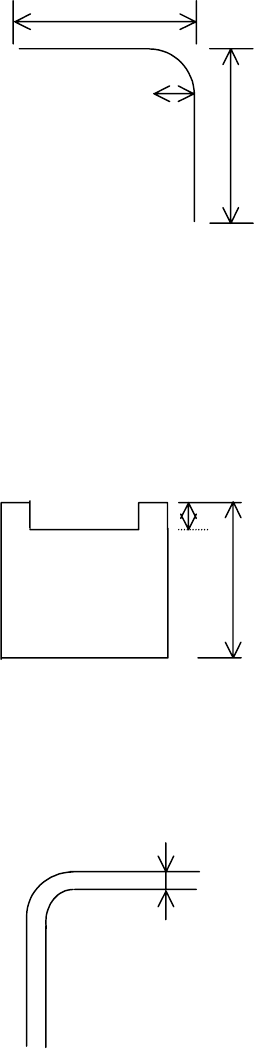
Recognition conditions:
① Components whose whole shape is a regular square or rectangle
② Components whose corner angle R is 0.5 mm or less
③ Components whose linear portion length forming each side is 2 mm or more
Fig. 6.4.2.1 Explanatory Drawing of Recognition Conditions ②
②②
② and ③
③③
③
④ Components whose 4 corner points are at vertexes of a regular square or
rectangle
⑤ Components whose outline is not convex
⑥ Components with concave portions whose L1 is 10% or less of L2
Fig. 6.4.2.2 Explanatory Drawing of Recognition Condition ⑥
⑦ Components whose sides are 0.3 mm or more when their insides are imaged
darkly at imaging
Fig. 6.4.2.3 Explanatory Drawing of Recognition Condition ⑦
⑦⑦
⑦
2.00mm
2.00mm
0.5mm
0.3 mm or more
L1
L2
6 − 25
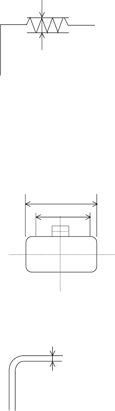
⑧ Components whose side roughness forming a linear portion is 0.1 mm or
less
Fig. 6.4.2.4 Explanatory Drawing of Recognition Condition ⑧
When the above recognition conditions are satisfied, corner recognition is enabled.
(2) Side recognition
① Components whose whole shape is a rectangle or regular square
② Components whose linear portion (line segment) of a side is 1/2 or more of
the component outline size but whose linear portion (line segment) should be
3 mm or more
③ Components whose sides are 0.3 mm or more when their insides are
imaged darkly at imaging
Fig. 6.4.2.5 Explanatory Drawing of Recognition Conditions ①
①①
①, ②
②②
② and ③
③③
③
④ Components whose component angle is within 90± 0.5.
⑤ Components whose sides are 0.3 mm or more when their insides are
imaged darkly at imaging
Fig. 6.4.2.6 Explanatory Drawing of Recognition Condition ⑤
⑤⑤
⑤
0.1 mm or less
Component outline size
Line segment
1.5mm
1.5mm
0.3 mm or more
6 − 26
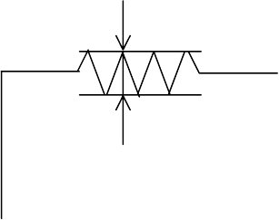
⑥ Components whose side roughness forming a linear portion is 0.1 mm or
less
Fig. 6.4.2.7 Explanatory Drawing of Recognition Condition ⑥
⑦ Components whose component shape is not convex.
When the above conditions are satisfied, side recognition is enabled.
(3) Center recognition
Recognition conditions
① Components whose ratio of width to length is 1:2 or more
② Components whose side portion is 0.3 mm or more (The inside of a side
may be hollow at imaging.)
When the above conditions are satisfied, center recognition is enabled.
Note: Concavity and convexity may exit on the component outline. However,
they have an effect on the center position and inclination.
In this case, adjust the placement data, etc.
0.1 mm or less