KJ-01.02.Instruction Manual.REV.02.pdf - 第59页
3 − 2 3.2 Turni ng Pow er ON 3.2.1 Operation sequence from power-on Turn on the pow er switch (break er). Press the Î } Í key . T o execute the warm-up oper ation, select 5/[W arm- up] f rom 1/[Maintenance] which is sele…
3 − 1
CHAPTER 3 OPERATION CHECK
3.1 Installation Check
CAUTION
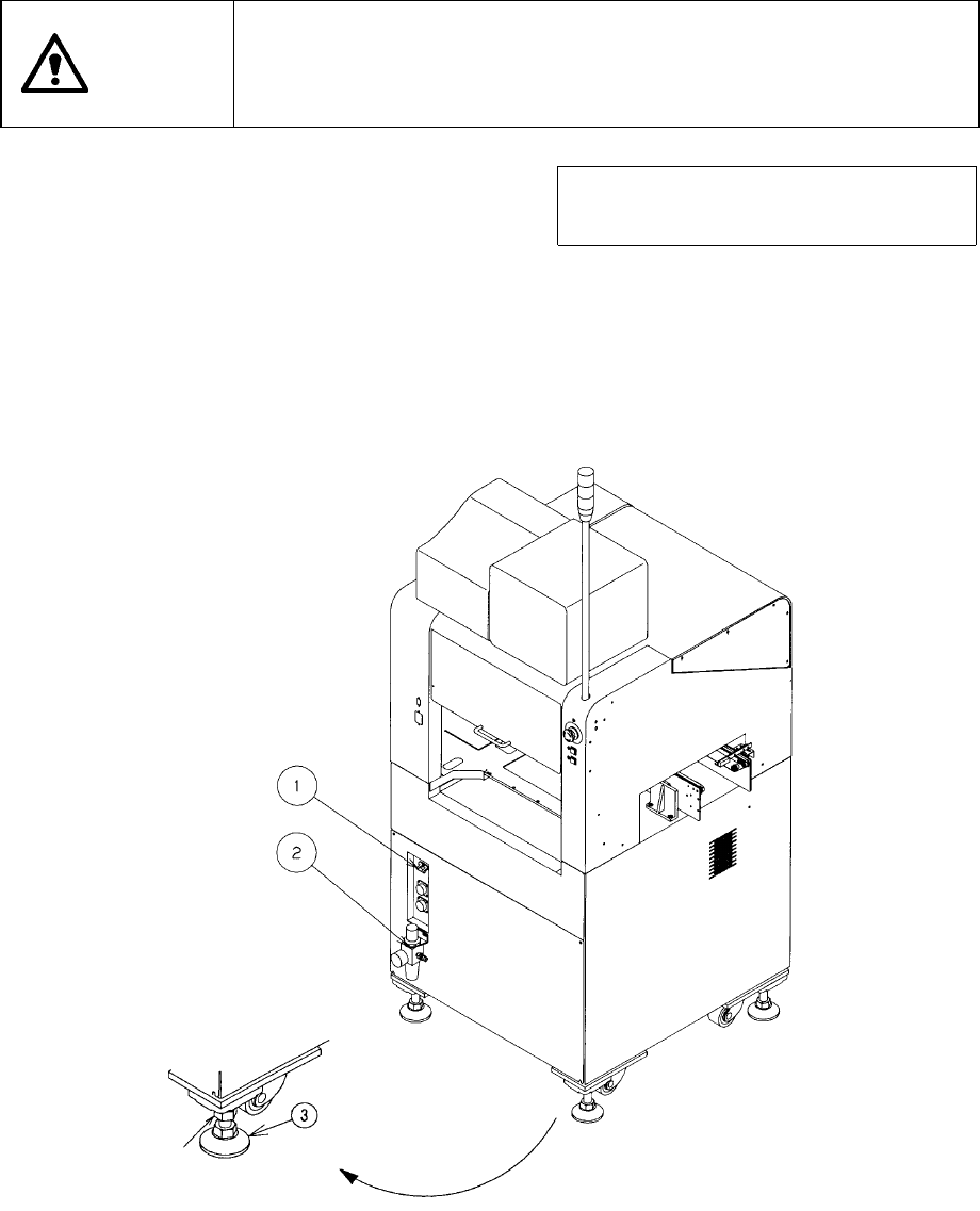
Check that the machine is level lying completely flat on the floor.
Check that the lock nuts are tightened securely on the four feet of the
machine.
Check that correct electrical power and air are supplied to the machine.
Note: To avoid the laser sensor detection
error, install the machine where not
subject to direct sunlight.
① Circuit breaker
② Filter regulator
③ Adjuster
Figure 3.1.1
3 − 2
3.2 Turning Power ON
3.2.1 Operation sequence from power-on
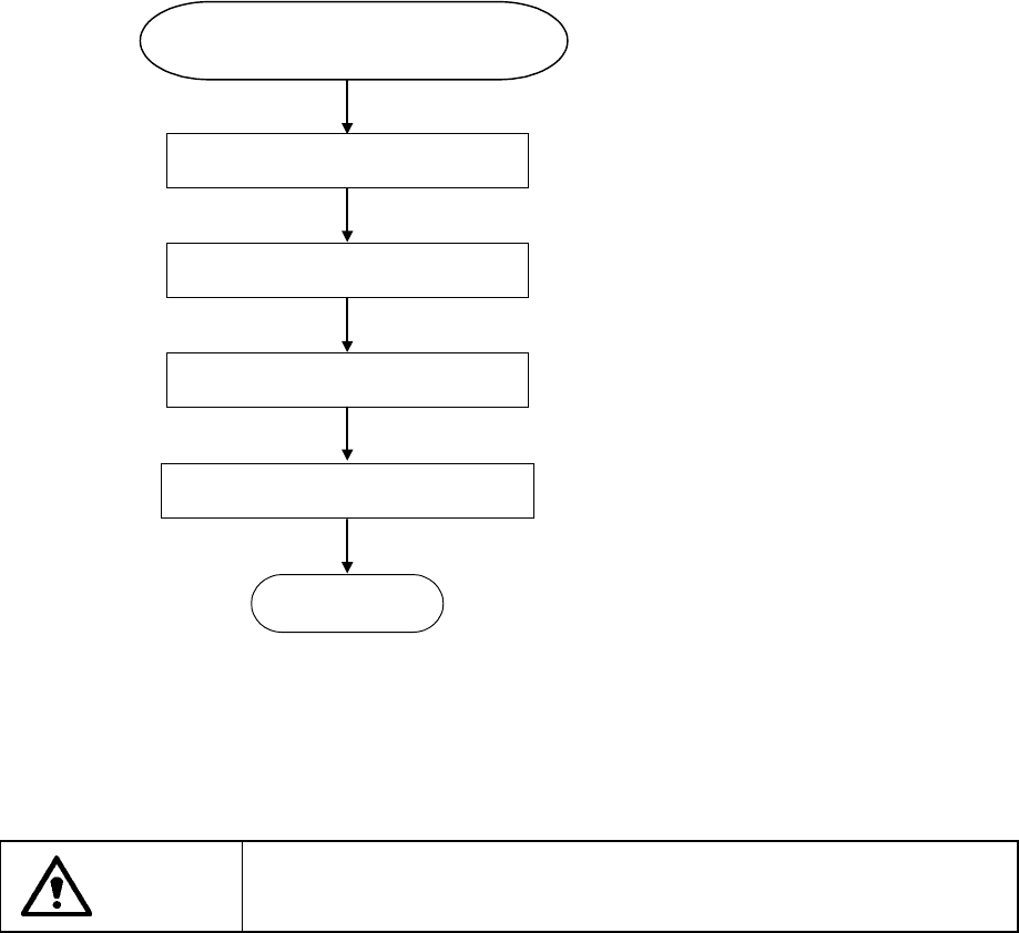
Turn on the power switch (breaker).
Press the Î
}
Í key.
To execute the warm-up operation,
select 5/[Warm-up] from
1/[Maintenance] which is selected
from the main menu.
Figure 3.2.1
CAUTION
Never operate the machine with any power voltages other than those
specified by the company.
Power ON
Menu on display
Zeroing
Select warm-up
READY
Operation sequence from
3 − 3
3.2.2 Checking circuit protector
If the machine does not operate properly after it has been turned ON, check the
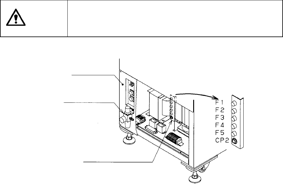
condition of the circuit protector (CP2) and fuse (F1 to F5) in the power unit found on
the back side of the machine. To check the condition of the circuit protector or that of
the fuses, remove the under cover RB and filter regulator.
If the circuit protector front face protrudes to show the red mark, push the face back in.
Set the CP5 switch to ON. If the fuse is burnt out, replace it with a new one.
To check the fuses (F1 to F5), turn the groove of the fuse holder with a flat-blade driver
to the left while pushing it gently, and then take them out. Be sure to replace the fuse
with a new one of the same rating.
The circuit protector and each fuse are located in the following power supply
systems:
F1: Power supply for a monitor
F2: Power supply for driving the motor of the PWB transport device
F3: Power supply for the switching device
F4: Power supply for driving the motor of the AC servo driver X
F5: Power supply for driving the motor of the AC servo driver Y
CP2: Power supply for driving the motor of the FMLA driver
CAUTION
To avoid a risk of serious injury or death caused by electric shock
hazard, turn off the main power switch of the house current which is
installed in the building where the machine is used.
Note that it is not the main power switch of the machine.
Figure 3.2.2
Filter regulator
Under cover RB
Circuit protector and fuses